Needle cover for medical injection device

A technology for an injection device and a needle shield, which is applied in the field of needle shields and can solve problems such as the inability to remove the needle shield and the treatment of the injection device.

Pending Publication Date: 2021-06-04
BECTON DICKINSON FRANCE
View PDF10 Cites 0 Cited by
  • Summary
  • Abstract
  • Description
  • Claims
  • Application Information

AI Technical Summary

Problems solved by technology

[0007] As a result, a user with reduced strength, for example weakened by disease, may not be able to remove the needle shield and use the injection device for his treatment

Method used


Image

  • Needle cover for medical injection device
  • Needle cover for medical injection device
  • Needle cover for medical injection device

Examples


example 1

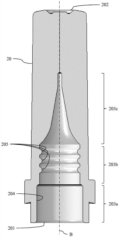
[0094] Three different designs of inner needle shield 20 (designated M) were molded from thermoplastic elastomer. exist Figure 4 These inner needle shields are shown in . The characteristics of these needle shields are described below and in Table 1.

[0095]

[0096] Table 1: Molded Needle Shields

[0097] "Radius" (R) refers to the radius (width) of each rib; "Height" (H) refers to the height of each rib; "Gap" (G) refers to the distance between two adjacent ribs; And "D" refers to the inner diameter of the inner needle shield at the inner sealing portion. For ribbed designs, when the inner needle shield is not inserted over the tip of the syringe, the diameter is measured at the top of the rib, as Figure 4 shown in . For all designs M1 , M2, M3 the needle shield was made of thermoplastic elastomer (TPE) and the injection device was a glass syringe.

[0098] will also refer to Figures 5A to 5C describe Figure 4 Designs M1, M2, M3 shown in, Figures 5A to 5C...

example 2

[0120] Example 2: Development of different designs of the sealing surface of the needle shield

[0121] To investigate the effect of the dimensions of the ribs and their number on the pull-out force, a finite element analysis was performed. The properties of thermoplastic elastomer materials (similar to those molded in Example 1) were used for this finite element analysis. Simulate needle shield removal and calculate pull-out force.

[0122] A simulated design of the sealing portion of the needle shield is described in Table 3 below.

[0123]

[0124]

[0125] Table 3: Alternative designs of the sealing portion of the needle shield


PUM


Abstract

The present invention relates to a needle cover (2) for protecting a needle (3) mounted on a tip (10) of a medical injection device, wherein the tip (10) comprises a distal bulge (11), the needle cover comprising an inner needle shield (20) made of a material with elastomeric properties, the inner needle shield (20) comprising an inner sealing portion (203b) configured to sealingly contact the outer surface (110) of the bulge (11), characterized in that the inner sealing portion (203b) comprises one or more ribs (205) extending inwardly along the circumference of the inner sealing portion, at least one rib being a continuous rib in the form of a ring configured to provide a continuous contact with the outer surface of the bulge.

Description

technical field [0001] The present invention relates to a needle shield adapted to be mounted on the tip of a medical injection device for covering a needle attached to said medical injection device. The invention also relates to a medical assembly for delivering a medical composition to the body of a patient, said medical assembly comprising a medical injection device and a needle shield for closing the needle of said medical injection device. Background technique [0002] Medical injection devices such as syringes generally comprise a container for containing a medical composition, the container having an end piece in the form of a longitudinal tip defining a fluid path through which a medical solution is drawn from the container and / or the reservoir is drained. A needle is attached to the tip in order to pierce the patient's skin and perform the injection of the composition. [0003] To prevent any injury before final use, a needle shield is fitted over the tip so as t...

Claims


Application Information

Patent Timeline
Patent Type & Authority Applications(China)
IPC IPC(8): A61M5/32A61M5/31
CPCA61M5/3202A61M2005/3109
Inventor G·普吉S·奥兹特克
Owner BECTON DICKINSON FRANCE
Why Eureka
Try Eureka