
Elevator sliding guide shoe and machining process thereof

A technology for sliding guide shoes and elevators, which is applied in elevators, transportation and packaging, etc. It can solve problems such as inconvenient disassembly, detachment of shoe linings, excessive friction between sliding guide shoes and guide rails, etc., so as to facilitate disassembly and replacement, improve firmness, and avoid overall detachment effect

Pending Publication Date: 2021-06-08
安徽九纲机电有限公司
View PDF0 Cites 0 Cited by
  • Summary
  • Abstract
  • Description
  • Claims
  • Application Information

AI Technical Summary

Problems solved by technology

The sliding guide shoe is installed on the side, top edge and bottom edge of the elevator car or the car hanger. The structure of the existing sliding guide shoe is complicated, the installation of the shoe lining is not firm, and it is inconvenient to disassemble, which is not conducive to subsequent maintenance Replacement, when the elevator car moves up and down and the guide rail in the elevator shaft rubs against the shoe lining, it is easy to cause the shoe lining to detach, resulting in excessive friction between the sliding guide shoe and the guide rail. Therefore, we propose an elevator sliding guide shoe and its processing process, to solve the problems mentioned in the above background technology

Method used


Image

  • Elevator sliding guide shoe and machining process thereof
  • Elevator sliding guide shoe and machining process thereof
  • Elevator sliding guide shoe and machining process thereof

Examples


Embodiment 1

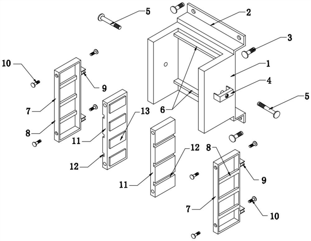
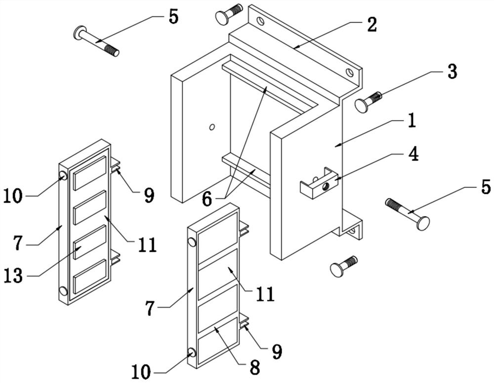
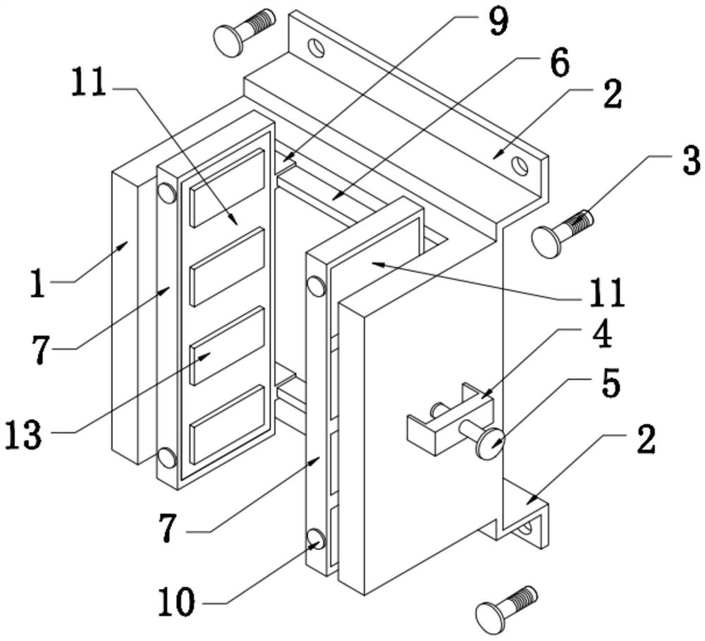
[0021] Embodiment 1: the present invention provides such as Figure 1-3 A sliding guide shoe for an elevator, comprising a shoe base 1, two sets of left and right installation frames 7 and shoe linings 11, the upper and lower parts of the inner rear side wall of the shoe base 1 are provided with slide rail plates 6, and the upper and lower parts of the installation frame 7 The upper and lower parts of the rear side are provided with a chute seat 9, and the chute seat 9 is slidably connected to the corresponding slide rail plate 6;

[0022] The inner side of the installation frame 7 is provided with several groups of stiffeners 8, the shoe lining 11 is stuck inside the installation frame 7, and the first bolt 10 on the side of the installation frame 7 is screwed to the shoe lining 11, so that The inner surface of the shoe lining 11 is provided with several sets of shoe lining protrusions 13 integrally formed therewith, and the shoe lining protrusions 13 are arranged equidistant...


PUM


Abstract

The invention discloses an elevator sliding guide shoe. The elevator sliding guide shoe comprises a shoe base, a left mounting frame, a right mounting frame and a shoe liner; sliding rail plates are arranged on the upper portion and the lower portion of the rear side wall in the shoe base; sliding groove bases are arranged on the upper portion and the lower portion of the rear side of each mounting frame; the sliding groove bases are connected to the corresponding sliding rail plates in a sliding manner; the shoe liner is clamped in the mounting frames; first bolts on the side edges of the mounting frames are in screw joint to the shoe liner; and long bolts penetrate the shoe base and then are in screw joint to a middle reinforcing rib plate. According to the elevator sliding guide shoe, the sliding groove bases are connected to the corresponding sliding rail plates in the sliding manner, and therefore when an elevator car moves up and down and a guide rail in an elevator shaft and the shoe liner generate friction, due to the fact that the sliding groove bases are connected to the corresponding sliding rail plates in the sliding manner, the up-down positions of the mounting frames can be limited, and then the mounting frames and the shoe liner are prevented from being integrally disengaged; and the shoe liner is clamped in the mounting frames, the first bolts on the side edges of the mounting frames are in screw joint to the shoe liner, and therefore the mounting firmness of the shoe liner and the mounting frames can be improved, and subsequent demounting and replacement are facilitated.

Description

technical field [0001] The invention belongs to the technical field of sliding guide shoes and, in particular, relates to an elevator sliding guide shoe and a processing technology thereof. Background technique [0002] Usually, the elevator comprises vertical guide rails arranged in the elevator shaft, by which guide rails the elevator car is adapted to run up and down in the elevator shaft. The sliding guide shoe is installed on the side, top edge and bottom edge of the elevator car or the car hanger. The structure of the existing sliding guide shoe is complicated, the installation of the shoe lining is not firm, and it is inconvenient to disassemble, which is not conducive to subsequent maintenance Replacement, when the elevator car moves up and down and the guide rail in the elevator shaft rubs against the shoe lining, it is easy to cause the shoe lining to detach, resulting in excessive friction between the sliding guide shoe and the guide rail. Therefore, we propose an...

Claims


Application Information

Patent Timeline
Patent Type & Authority Applications(China)
IPC IPC(8): B66B7/04B66B7/02
CPCB66B7/047B66B7/023B66B7/024B66B7/027
Inventor 许九刚
Owner 安徽九纲机电有限公司
Learn More