Supercharge Your Innovation With Domain-Expert AI Agents!

Novel hydraulic excavator piling device

A technology of hydraulic excavator and piling device, which is applied in the direction of sheet pile wall, building, foundation structure engineering, etc., and can solve the problems of small actual depth of soil pile pit, soil falling, loose soil, etc.

Inactive Publication Date: 2021-06-11
方波
View PDF0 Cites 0 Cited by
  • Summary
  • Abstract
  • Description
  • Claims
  • Application Information

AI Technical Summary

Problems solved by technology

[0003] Because part of the land contains a lot of sand, the soil inside the land will be relatively loose, and the hydraulic excavator piles the land vertically, so that when the hydraulic excavator vertically extends upwards, it is easy The loose soil on the inner wall of the pile pit will fall, causing the actual depth of the pile pit to be smaller than the required depth

Method used


Image

  • Novel hydraulic excavator piling device
  • Novel hydraulic excavator piling device
  • Novel hydraulic excavator piling device

Examples


Embodiment 1

[0026] For example figure 1 -example Figure 5 Shown:

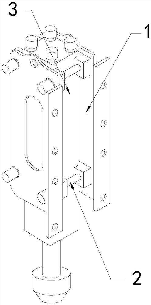
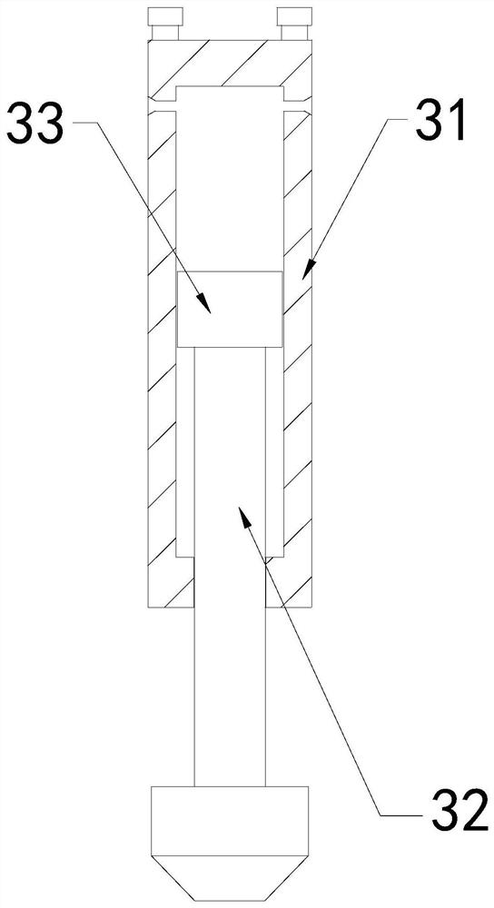
[0027] The present invention provides a new hydraulic excavator piling device, the structure of which includes an outer frame 1, a fixing screw 2, and a piling mechanism 3, the fixing screw 2 is connected to the inner thread of the outer frame 1, and the piling mechanism 3 penetrates the outer frame 1; the piling mechanism 3 includes an outer frame 31, a lower pressing rod 32, and a piston 33, and the lower pressing rod 32 is engaged with the inside of the outer frame 31; connected.

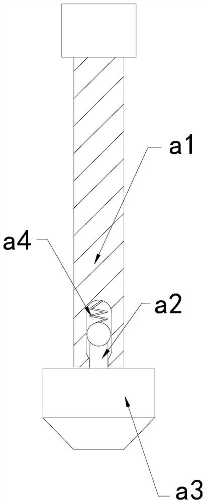
[0028] Wherein, the lower pressing rod 32 includes a rod body a1, a linkage rod a2, a bottom connecting block a3, and an elastic bar a4. The bottom of a2 fits together, and the elastic strip a4 is fixed on the upper end of the linkage rod a2 and the upper end of the inner wall of the rod body a1. Pulling the rod body a1 upwards through the mechanism can make the rod body a1 slide upward along the linkage rod a2, so that the bottom connect...

Embodiment 2

[0034] For example Image 6 -example Figure 8 Shown:

[0035] Wherein, the separating block b4 includes a rear frame b41, a sliding plate b42, and a reset bar b43, the sliding plate b42 is slidingly matched with the left side of the rear frame b41, and the reset bar b43 is installed on the inner wall of the rear frame b41 Between the sliding plate b42 and the sliding plate b42, there are two sliding plates b42, which are evenly distributed symmetrically on the left side of the rear frame b41. , the sliding plate b42 can be deployed to both sides along the rear frame b41, so that the sliding plate b42 can grind the inner wall of the soil pile pit.

[0036]Wherein, the sliding plate b42 includes a position fixing plate c1, an outer push piece c2, and an outer swing plate c3, and the outer push piece c2 is installed between the inner side of the outer swing plate c3 and the right side of the inner wall of the position fix plate c1. The outer swing plate c3 is hinged to the le...


PUM


Abstract

The invention discloses a novel hydraulic excavator piling device. The novel hydraulic excavator piling device structurally comprises an external connecting frame, a fixing screw and a piling mechanism; the fixing screw is connected to an internal thread of the external connecting frame, and the piling mechanism penetrates through the internal position of the external connecting frame; when a lower pressure rod descends, reverse thrust is generated by the bottom of a soil pile pit on two outer expansion plates, and the external expansion plates can slide and unfold outwards along a connecting frame so that the sides of the external expansion plates can compact the inner wall of the soil pile pit, thus the phenomenon that soil on the inner wall of the soil pile pit falls off when a lower pressing rod is completely pulled out is avoided, and the situation that soil on the inner wall of the soil pile pit containing much sand is prone to falling off is effectively avoided; and the inner wall of the soil pile pit extrudes the position between two sliding plates, the sliding plates can slide towards the two sides along a rear frame, therefore the sliding plates can flatten and compact the inner wall of the soil pile pit, and therefore, the lower pressing rod can be easily pulled out of the interior of the soil pile pit.

Description

technical field [0001] The invention relates to the field of hydraulic pressure and its equipment, in particular to a novel hydraulic excavator piling device. Background technique [0002] The hydraulic excavator piling column is mainly used for piling the land. By installing the hydraulic excavator piling column on the front end of the hydraulic excavator, the hydraulic rod on the hydraulic excavator piling column pushes the pressure rod down into the land. , after the pressure rod drops to the required depth, the pressure rod is pulled up by the hydraulic rod, so that the pressure rod can take the soil inside the soil pile hole out, so the soil pile hole of the required depth can be obtained, based on The above description The inventors found that the existing piling device for a new hydraulic excavator mainly has the following deficiencies, for example: [0003] Because part of the land contains a lot of sand, the soil inside the land will be relatively loose, and the hy...

Claims


Application Information

Patent Timeline
Patent Type & Authority Applications(China)
IPC IPC(8): E02D7/06E02D7/14E02D13/02
CPCE02D7/06E02D7/14E02D13/02
Inventor 方波
Owner 方波
Features
  • R&D
  • Intellectual Property
  • Life Sciences
  • Materials
  • Tech Scout
  • Unparalleled Data Quality
  • Higher Quality Content
  • 60% Fewer Hallucinations
Learn More