

Working table low-speed motion control method and system applied to DMD system
A low-speed movement and control method technology, applied in the direction of instruments, optics, optical components, etc., to achieve the effect of improving resolution, high repetition frequency, and high efficiency
Image

Examples
Embodiment Construction
[0044] In order to make the purpose, technical solutions and advantages of the present invention clearer, the technical solutions in the embodiments of the present invention will be clearly and completely described below in conjunction with the accompanying drawings in the embodiments of the present invention. Obviously, the described embodiments are only Some, but not all, embodiments of the invention. Based on the embodiments of the present invention, all other embodiments obtained by persons of ordinary skill in the art without making creative efforts belong to the protection scope of the present invention.
[0045] On the one hand, the embodiment of the present invention discloses a low-speed motion control method applied to a DMD system workbench, including the following steps:
[0046] S1. Perform data processing on the large-format processing graphics to generate corresponding grayscale graphics;
[0047] S2. Divide the grayscale graphic into several grayscale graphic ...
PUM
| Property | Measurement | Unit |
|---|---|---|
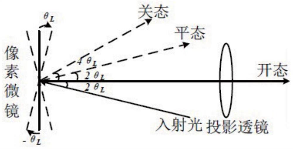
| angle of incidence | aaaaa | aaaaa |
Abstract
Description
Claims
Application Information
- IPC
- G02B26/08; G02F1/1337
- CPC
- G02B26/0833; G02F1/133788
- Inventors
- 黄文彬; 郑致刚