Eureka AIR delivers breakthrough ideas for toughest innovation challenges, trusted by R&D personnel around the world.

Touch panel and display device

A touch panel and touch technology, applied in the direction of instruments, electrical digital data processing, input/output process of data processing, etc., can solve problems such as structural differences, touch panel touch performance degradation, etc., to improve touch performance Effect

Active Publication Date: 2021-06-11
WUHAN CHINA STAR OPTOELECTRONICS SEMICON DISPLAY TECH CO LTD
View PDF11 Cites 0 Cited by
  • Summary
  • Abstract
  • Description
  • Claims
  • Application Information

AI Technical Summary

Problems solved by technology

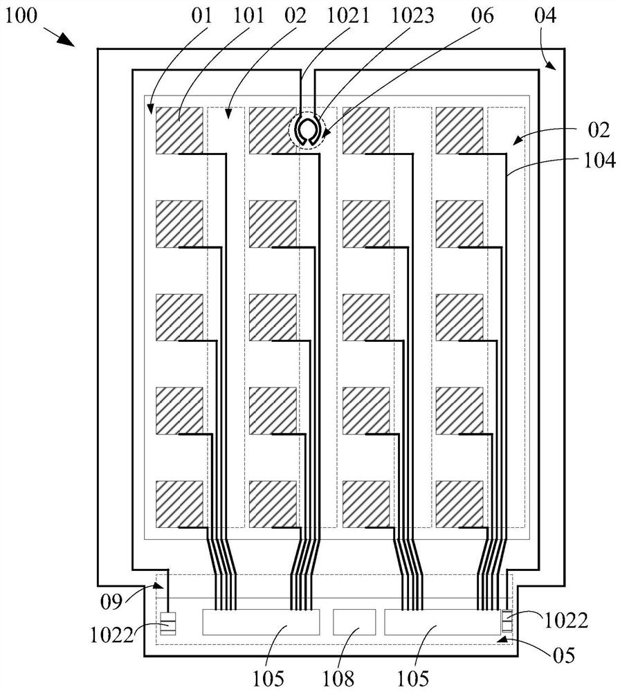
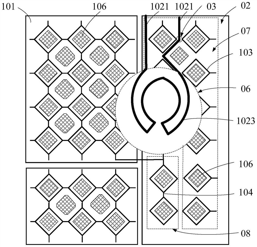
[0004] The embodiment of this application provides a touch panel and a display device to solve the problem that the existing detection circuit and a large number of touch blocks are arranged on the same layer and span part of the touch blocks , resulting in differences in the structure of some touch blocks and other touch blocks, resulting in a decrease in the touch performance of the touch panel

Method used


Image

  • Touch panel and display device
  • Touch panel and display device

Examples


Embodiment Construction

[0027] The following will clearly and continuously describe the technical solutions in the embodiments of the present application with reference to the drawings in the embodiments of the present application. Apparently, the described embodiments are only some of the embodiments of this application, not all of them. Based on the embodiments in this application, all other embodiments obtained by those skilled in the art without making creative efforts belong to the scope of protection of this application.

[0028] In the description of the present application, it should be understood that the orientation or positional relationship indicated by the terms "surrounding", "extending", "row", "column", etc. is based on the orientation or positional relationship shown in the drawings, and is only for the purpose of It is convenient to describe the application and simplify the description, but not to indicate or imply that the device or element referred to must have a specific orientat...


PUM


Abstract

The invention discloses a touch panel and a display device, the touch panel and the display device comprise a display area, the touch panel comprises a plurality of touch blocks, wherein one side of each column of touch blocks is provided with a corresponding blind area, and the plurality of touch blocks and the plurality of blind areas are all located in the display area; and a test circuit comprising test lines, wherein the test lines are located in the corresponding blind area; according to the scheme, the test lines can be prevented from crossing the touch blocks, so that the structural difference between part of the touch blocks and other touch blocks is avoided, and the touch performance of the touch panel and the display device is improved.

Description

technical field [0001] The present application relates to the field of display technology, in particular to the field of display panel manufacturing technology, in particular to a touch panel and a display device. Background technique [0002] In the under-display camera technology, laser cutting is usually used to form a through hole to place the camera. Laser cutting is prone to cracks and leads to circuit breakage, so the detection circuit is particularly important. [0003] Among them, since the mutual capacitive touch panel includes a bridging layer arranged on a different layer from the touch electrodes, the detection circuit can be arranged on the same layer as the bridging layer to avoid straddling the touch electrodes; however, a large number of touch electrodes in the self-capacitive touch panel The control blocks are all set on the same layer, and the detection circuit and a large number of touch blocks are set on the same layer across some touch blocks, resulting...

Claims


Application Information

Patent Timeline
Patent Type & Authority Applications(China)
IPC IPC(8): G06F3/041
CPCG06F3/0412G06F3/04164
Inventor 方亮丁玎
Owner WUHAN CHINA STAR OPTOELECTRONICS SEMICON DISPLAY TECH CO LTD
Why Eureka
Eureka Blog
Learn More