Flexible display device

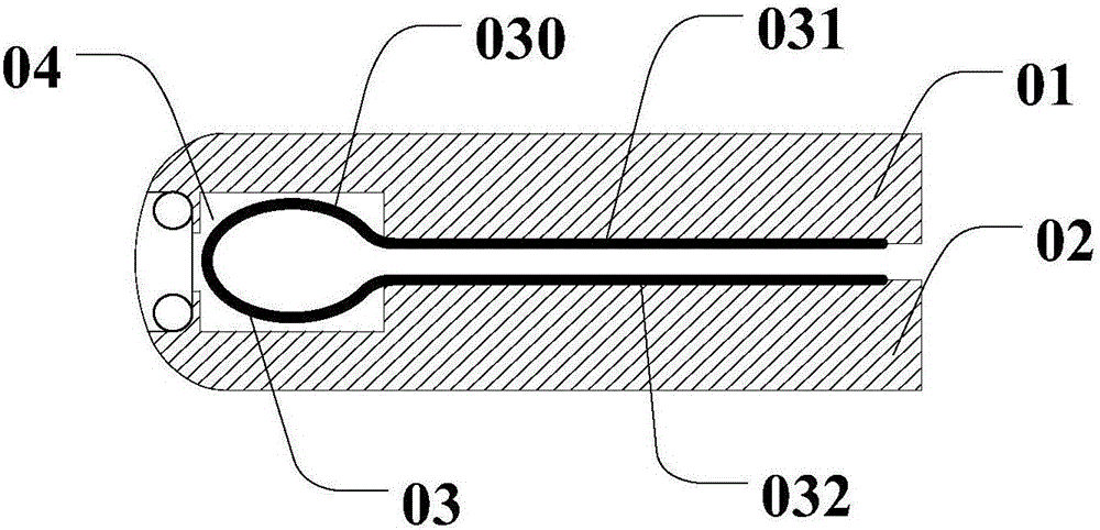
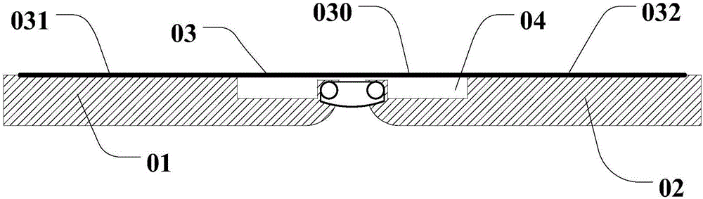
A flexible display device, flexible display technology, applied in the direction of identification devices, instruments, etc., can solve the problems of poor touch performance and easy damage of the bending part 030, so as to improve touch performance, increase service life, and reduce damage Effect

Active Publication Date: 2017-06-13
SHANGHAI TIANMA MICRO ELECTRONICS CO LTD
View PDF5 Cites 19 Cited by
  • Summary
  • Abstract
  • Description
  • Claims
  • Application Information

AI Technical Summary

Problems solved by technology

[0004] When the flexible display device is working, the flexible display screen is in a flattened state, and the curved portion 030 of the flexible display screen 03 is opposite to the storage groove 04. Therefore, there is no support under the curved portion 030 of the flexible display screen 03, and it is easy to be bumped. In particular, when the flexible display screen 03 is a touch screen, when the user performs a touch operation, not only is it easy to damage the curved portion 030 of the flexible display screen 03, but also the curved portion 030 has poor touch performance.

Method used


Image

  • Flexible display device
  • Flexible display device
  • Flexible display device

Examples


Embodiment 1

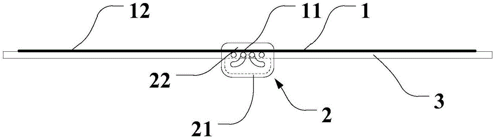
[0060] Such as image 3 , Figure 4 and Figure 5As shown, the flexible display device provided by Embodiment 1 of the present invention includes a flexible display screen 1, a connector 2 and two support plates 3, wherein the flexible display screen 1 includes a curved portion 11 and two The planar part 12; the connector 2 is arranged opposite to the curved part 11, including a bottom plate 21 and a pair of end plates 22 connected to the bottom plate 21 and positioned opposite; the two support plates 3 are respectively connected to the first sides of the two planar parts 12 and Located between a pair of end plates 22, the two support plates 3 and the pair of end plates 22 are respectively hinged at the position of the first hinge axis 27 and the position of the second hinge axis 28. When the flexible display screen 1 is in the flattened state, the two The support plate 3 abuts against and fits with the connecting member 2 to form a plane for supporting the flexible display ...

Embodiment 2

[0073] Such as Figure 10 As shown, compared with the first embodiment, the second embodiment has made some changes in the structure of the connecting piece 2, specifically, each end plate 22 of the connecting piece has two first stop protrusions 24, when the flexible When the display screen 1 is in the flattened state, the two first limit protrusions 24 abut against the sides of the two support plates 3 close to the flexible display screen 1 respectively, and the two support plates 3 are combined to form a support for the flexible display screen 1 . flat. When the flexible display screen 1 is in the flattened state, the two first limiting protrusions 24 respectively abut against the sides of the two support plates 3 close to the flexible display screen 1 .

[0074] For this embodiment, the two first position-limiting protrusions 24 are located on the side of the two support plates 3 close to the flexible display screen 1, and the size of the flexible display screen 1 needs t...

Embodiment 3

[0077] Such as Figure 11 As shown, compared with the first embodiment, the third embodiment has made some changes in the structure of the connector, and each end plate 22 has two second limit protrusions 25; when the flexible display screen 1 is in the flattened state At this time, the two second position-limiting protrusions 25 abut against the sides of the two support plates 3 away from the flexible display screen 1 respectively, and the two support plates 3 are combined to form a plane for supporting the flexible display screen 1 . When the flexible display screen 1 is in the flattened state, the two second limiting protrusions 25 respectively support the two support plates 3 on the sides of the two support plates 3 away from the flexible display screen 1 .

[0078] In addition, please continue to refer to Figure 11 , each end plate 22 has two third limit protrusions 26; side abutment, so that the folded state of the flexible display device is more stable.

[0079] In ...


PUM


Abstract

The invention discloses a flexible display device so as to reduce damage to a bent part of a flexible display screen, which is caused by an external force, and improve a service life of the flexible display screen. The flexible display device comprises a flexible display screen, a connecting piece and two supporting plates, wherein the flexible display screen comprises a bent part and two plane parts positioned at both sides of the bent part; the connecting piece is arranged opposite to the bent part and comprises a bottom plate and a pair of end plates which are connected with the bottom plate and are opposite to each other in position; two supporting plates are respectively connected with first sides of two plane parts and are positioned between the pair of end plates; two supporting plates and the pair of end plates are respectively hinged at a first hinged axis position and a second hinged axis position; when the flexible display screen is in a flattened state, two supporting plates and the connecting piece are abutted and are closed oppositely to form a plane for supporting the flexible display screen.

Description

technical field [0001] The invention relates to the field of display technology, in particular to a flexible display device. Background technique [0002] Flexible display screens have many features that traditional display screens do not have, such as thinness, impact resistance, and rollability, which can make display devices thinner, lighter, more portable, and more stylish, providing them with a broader space for development. Therefore, in the display fields such as electronic paper and active matrix organic light-emitting diodes, flexible display technologies represented by flexible display screens have received extensive attention and research. [0003] In the prior art, a commonly used flexible display storage method is folding, such as figure 1 and figure 2 As shown, there is an existing flexible display device, which includes: a first housing 01 and a second housing 02 that are folded and connected, and the connection between the first housing 01 and the second h...

Claims


Application Information

Patent Timeline
Patent Type & Authority Applications(China)
IPC IPC(8): G09F9/30
Inventor 何永新袁世鹏
Owner SHANGHAI TIANMA MICRO ELECTRONICS CO LTD
Why Eureka
Try Eureka