Seasoning automatic mashing device

Active Publication Date: 2021-11-23
重庆市永川职业教育中心
View PDF9 Cites 0 Cited by
  • Summary
  • Abstract
  • Description
  • Claims
  • Application Information

AI Technical Summary

Problems solved by technology

[0003] The present invention intends to provide an automatic seasoning mashing device to solve the problem of inconvenient discharge from the mashing tank in the existing mashing device

Method used


Image

  • Seasoning automatic mashing device
  • Seasoning automatic mashing device
  • Seasoning automatic mashing device

Examples


Embodiment 1

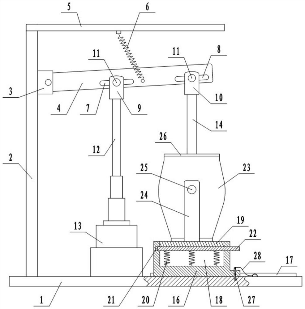
[0033] This embodiment is basically as figure 1 Shown: the seasoning automatic smashing device, including a base 1, a bracket 2 is welded on the base 1, the top of the bracket 2 is fixedly connected with a fixed block 3 by bolts, and the fixed block 3 is hinged with a swing plate 4. In this embodiment, the swing plate The left end of 4 is hinged on the fixed block 3 by pin shaft. A horizontal plate 5 is welded on the top of the support 2, a return spring 6 is welded on the transverse plate 5, and the bottom end of the return spring 6 is welded to the swing plate 4.

[0034] The middle part of the swing plate 4 is provided with a waist hole 17 arranged along the length direction of the swing plate 4, and the right end of the swing plate 4 is provided with a waist hole 2 8 arranged along the length direction of the swing plate 4, and the waist hole 17 is slidingly connected. There is a mounting block 19, and a mounting block 10 is slidably connected in the waist round hole 28. ...

Embodiment 2

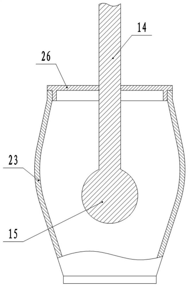
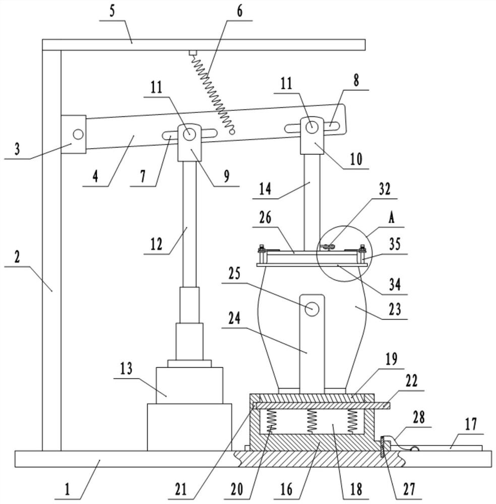
[0043] The difference between this embodiment and Embodiment 1 is that: image 3 , Figure 4 and Figure 5 As shown, the stamping hammer 15 is provided with some vertical passages 29, and in the present embodiment, the number of passages 29 is five ( Figure 4 Only three passages 29 can be seen in the middle passage 29, and the other two passages 29 are located at the front side and the rear side of the middle passage 29), the inside of the hammer rod 14 is provided with a cavity 30, the cavity 30 is an inverted L shape, and the cavity 30 There are five pushing rods 31 corresponding to the passages 29, the bottom ends of the pushing rods 31 extend into the corresponding passages 29, and the tops of the pushing rods 31 are jointly welded with a transverse piece 32, and the transverse piece 32 extends out of the cavity 30 . A T-shaped connecting piece 33 is welded on the cover plate 26 , and the connecting piece 33 and the transverse piece 32 are detachably connected by bolts...

Embodiment 3

[0048] The difference between the present embodiment and the second embodiment is that in the present embodiment, the driving member 13 is a push rod motor, and since the push rod motor can drive the drive rod 12 to move up and down, it is not necessary to design the horizontal plate 5 and the return spring 6 .


PUM


Abstract

The invention relates to the field of crushing devices, and discloses an automatic seasoning crushing device, which includes a base, a bracket is arranged on the base, a fixed block is fixedly connected to the bracket, a swing plate is hinged to the fixed block, and a mounting block is slidably connected to the swing plate. and the installation block two, the installation block one and the installation block two are hinged with the swing plate, the base is provided with a driver for driving the vertical movement of the installation block one, the installation block two is connected with a hammer rod, and the bottom end of the hammer rod is set There is a tamper; there is a boss on the base, and a groove is opened on the boss, and a slider is vertically slid in the groove, and a plate for limiting the slider is also arranged on the boss. In the crushing tank, the pounding hammer is located in the crushing tank, and the crushing tank is rotatably connected to a mounting plate fixed on the boss through a rotating roller. In the present invention, when the slider and the inserting plate are in contact with each other, the mashing tank is fixed, and the smashing tank can be released by pulling the inserting plate away, which is convenient for the user to dump the mashing tank for material extraction, that is, the material is convenient to discharge , High discharge efficiency.

Description

technical field [0001] The invention relates to the field of crushing devices, in particular to a seasoning automatic crushing device. Background technique [0002] At present, seasonings such as dried chili or garlic are usually mashed by a mashing device. The above mashing device usually includes a mashing hammer and a mashing tank. Move up and down to mash the raw materials in the mash tank. During the mashing process of raw materials, in order to avoid the movement of the mashing pot, the mashing pot is usually fixed on the base, and the range of motion of the hammer is usually in the mashing pot, which can prevent the mashing hammer from being carried out of the mashing pot Raw materials lead to leakage of raw materials. However, such a setting will cause more troublesome discharge of materials. It is necessary to release the fixed state of the mashing tank, then manually dump the mashing tank, remove the mashing tank, and finally take out the raw materials in the mas...

Claims


Application Information

Patent Timeline
Patent Type & Authority Patents(China)
IPC IPC(8): A47J19/00A47J19/04
CPCA47J19/00A47J19/04
Inventor 王平张安彬王鸿君罗桥欧汉文
Owner 重庆市永川职业教育中心
Why Eureka
Try Eureka