
Novel intelligent projection device

A technology of intelligent projection and equipment, which is applied in the direction of using projection device image reproducer, color TV parts, TV system parts, etc., can solve the problems of low efficiency and manpower consumption, and achieve convenient angle, stable operation, Enhance the effect of the scope of application

Inactive Publication Date: 2021-06-22
厦门穆寒科技有限公司
View PDF1 Cites 0 Cited by
  • Summary
  • Abstract
  • Description
  • Claims
  • Application Information

AI Technical Summary

Problems solved by technology

[0005] The purpose of the present invention is to solve the problem of labor-intensive and low efficiency in the prior art, and propose a new type of intelligent projection equipment

Method used


Image

  • Novel intelligent projection device
  • Novel intelligent projection device
  • Novel intelligent projection device

Examples


Embodiment 1

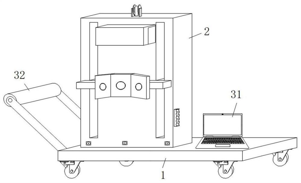
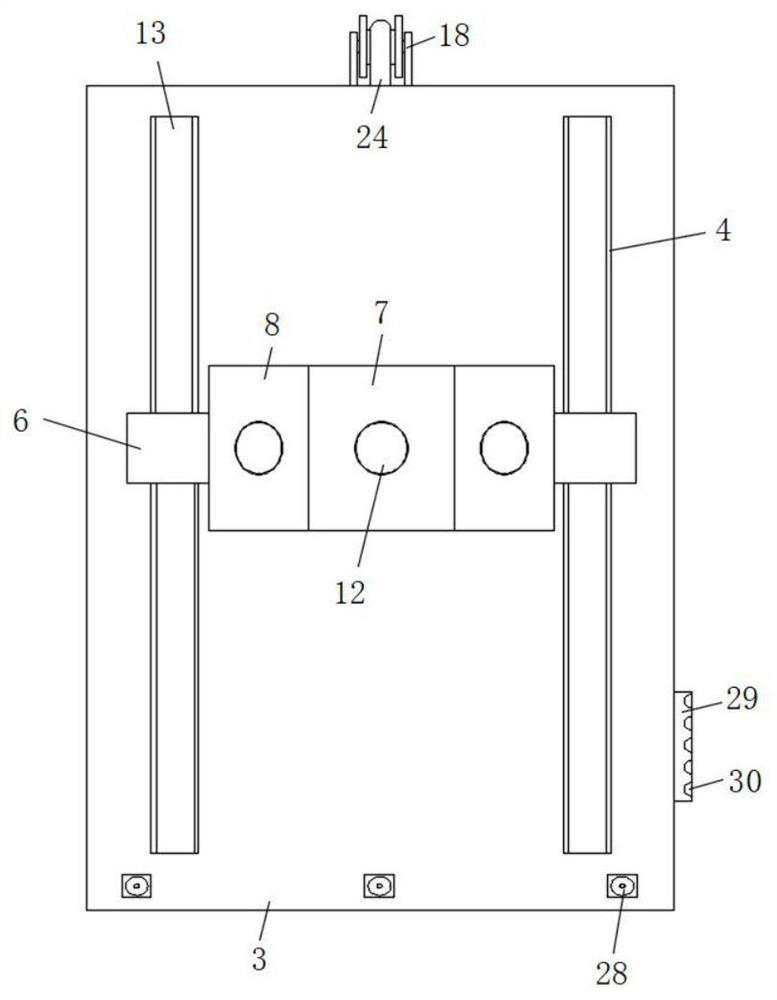
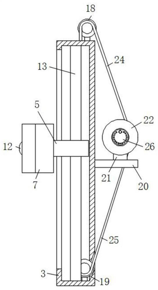
[0034] refer to Figure 1-8 , a new type of intelligent projection equipment, including a base 1, universal wheels are installed at the four corners of the bottom surface of the base 1, a photographic mechanism 2 is installed on one side of the top surface of the base 1, the photographic mechanism 2 includes a mounting dish 3, and the mounting dish 3 The front faces are all provided with strip grooves 4, and the inner walls of the strip grooves 4 are slidingly connected with strip blocks 5, and the front ends of the two strip blocks 5 are fixedly connected with mounting strips 6 by screws, and the middle part of the front ends of the mounting strips 6 is fixedly connected with a mounting strip 5. Block 1 7 and mounting block 2 8, the center of the front end of mounting block 1 7 and mounting block 2 8 are provided with a mounting hole, the inner bottom of the mounting hole is welded with U-shaped block 9, between the inner bottom surface and the top surface of U-shaped block 9 ...

Embodiment 2

[0037] like figure 1 and 2 As shown, this embodiment is basically the same as Embodiment 1. Preferably, a cable clamping tray 29 is fixed on the lower side of the installation dish 3 near the end of the computer 31 , and the side wall of the cable clamping tray 29 is provided with a cable clamping groove 30 .

[0038] There are a plurality of wire clamping slots 30 which are evenly distributed on the side wall of the wire clamping tray 29, and the wire clamping slots 30 are also provided with various specifications.

[0039] In this embodiment, the wire clamping disc 29 is fixed on the side wall of the installation dish 3, and the side wall of the clamping disc 29 is provided with various specifications of the clamping grooves 30, so that the wiring of the equipment is more orderly during installation, and the equipment assembly is easier. Stablize.

Embodiment 3

[0041] like figure 1 and 4 As shown, this embodiment is basically the same as Embodiment 1. Preferably, the installation block one 7 is fixed at the center of the front end of the installation bar 6, and two installation blocks 8 are provided and distributed on both sides of the installation block one 7. Mounting block two 8 front ends are all obliquely set by mounting bar 6 outsides to mounting bar 6 center one side in view.

[0042] In this embodiment, the front end of the mounting block 2 8 is inclined from the outside of the mounting bar 6 to the center side of the mounting bar 6, so that the images projected by the three projection cameras 12 can overlap smoothly.


PUM


Abstract

A novel intelligent projection device disclosed by the present invention comprises a base, universal wheels are installed at the four corners of the bottom surface of the base, a photographing mechanism is installed on one side of the top surface of the base, and the photographing mechanism comprises a mounting vessel. Strip-shaped grooves are formed in the front end faces of the mounting dishes, strip-shaped blocks are slidably connected to the inner walls of the strip-shaped grooves, mounting strips are fixedly connected to the front ends of the two strip-shaped blocks through screws, a first mounting block and a second mounting block are fixedly connected to the middles of the front end faces of the mounting strips, and mounting holes are formed in the centers of the front end faces of the first mounting block and the second mounting block. A U-shaped block is welded on the inner bottom surface of the mounting hole. A connecting block I is rotationally connected between the inner bottom surface and the top surface of the U-shaped block in a damping manner. The upper and lower end of the front side of the connecting block are connected to a rectangular grove, and the inner walls of the front side and the rear side of the rectangular groove are rotationally connected with second connecting block in a damping mode. The device is reasonable in design and stable in operation, the phenomenon that people or objects block the camera can be well avoided, and the image projection quality of the projection equipment is well guaranteed.

Description

technical field [0001] The present invention relates to the technical field of projection equipment, in particular to a novel intelligent projection equipment. Background technique [0002] Projection equipment is a device that can project images or videos onto the screen. It can be connected to computers, VCD, DVD, BD, game consoles, DV, etc. through different interfaces to play corresponding video signals. With the progress of society And development, projection equipment is widely used in homes, offices, schools and entertainment places, so the research on projection equipment is very important. [0003] After retrieval, the patent application number 202020975882.4 discloses an intelligently controlled projection device, including a projector. The bottom of the projector is fixedly equipped with an angle adjustment base, and the front and back sides of the left and right sides of the angle adjustment base are respectively fixedly connected with support columns. The top a...

Claims


Application Information

Patent Timeline
Patent Type & Authority Applications(China)
IPC IPC(8): H04N9/31H04N5/225
CPCH04N9/3141H04N23/50H04N23/57
Inventor 李永
Owner 厦门穆寒科技有限公司
Learn More