Auxiliary unloading equipment for express transport vehicle

A technology for transport vehicles and equipment, which is applied to vehicles with screw conveyors, etc., which can solve the problems of heavy physical exertion and heavy workload for staff, and achieve the effects of reducing workload, improving loading efficiency, and preventing goods from falling

Inactive Publication Date: 2021-06-25
周木森
View PDF0 Cites 1 Cited by
  • Summary
  • Abstract
  • Description
  • Claims
  • Application Information

AI Technical Summary

Problems solved by technology

When the transport vehicle arrives at the destination to unload the goods, it is generally divided into two situations: first, the courier personnel will directly throw the package out of the outside of the compartment without special requirements, and then sort it; in the case of a shortage of courier personnel Next, the delivery of parcels to the outside of the carriage and the sorting of parcels are all done by the couriers in the sub-area, with a large workload
Second, the transport personnel artificially put the parcels on the conveyor belt, and transport them to the ground for sorting through the conveyor belt; in this case, one end of the conveyor belt needs to be placed in the compartment first, and then two to three people need to stand in the compartment Manually place the package on the conveyor belt; the physical exertion of the staff is relatively high

Method used


Image

  • Auxiliary unloading equipment for express transport vehicle
  • Auxiliary unloading equipment for express transport vehicle
  • Auxiliary unloading equipment for express transport vehicle

Examples


Embodiment Construction

[0047] The specific implementation manners of the present invention will be further described in detail below in conjunction with the accompanying drawings and embodiments. The following examples or drawings are used to illustrate the present invention, but not to limit the scope of the present invention.

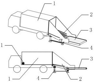
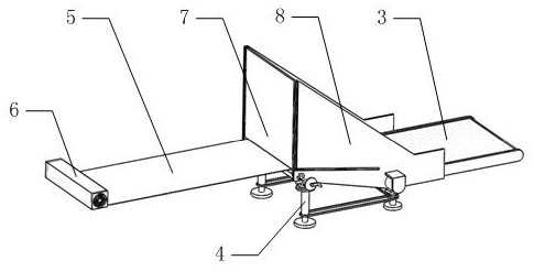
[0048] like figure 1 , 2As shown, it includes an unloading module 2, a conveyor belt 5, and a winding mechanism 6, wherein the winding mechanism 6 is installed on the bottom surface of the compartment 1 and is close to the front of the vehicle.

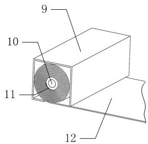
[0049] like image 3 , 4 As shown, the above-mentioned winding mechanism 6 includes an installation shell 9, an installation shaft 10, a winding roller 11, and a scroll spring 13, wherein the installation shaft 10 is rotatably installed in the installation shell 9, and the winding roller 11 is fixedly installed on the installation shaft 10; two The scroll spring 13 is installed symmetrically at both ends of the installation sha...


PUM


Abstract

The invention belongs to the technical field of express unloading, and particularly relates to an auxiliary unloading device for an express transport vehicle, which comprises an unloading module, a conveying belt and a winding mechanism, and the winding mechanism is mounted on the bottom surface in a compartment and is close to a vehicle head. A front baffle is designed, and after the rear door of the carriage is opened, the front sides of the two side baffles in the unloading module are close to the rear end of the carriage, so that the front baffle is attached to the end face of the rear end of the carriage. Then the front baffle is driven to swing downwards, so that the parcels close to the rear door of the carriage in the carriage slowly move downwards along with the front baffle, and the phenomenon that the parcels fall from a high place is avoided; and the package is protected. The two side baffles are designed, the two side baffles play a role in guiding and limiting parcels driven by the conveying belt to move, and the parcels are prevented from sliding off from the two sides. The winding mechanism and the conveying belt are flatly laid on the bottom plate of the carriage, so that the occupied space in the carriage is very small, and the loading efficiency is improved.

Description

[0001] Technical field [0002] The invention belongs to the technical field of express unloading, and in particular relates to equipment for assisting unloading of an express transport vehicle. Background technique [0003] At present, there are generally three modes of transportation: the first is air transport, which is also the most important mode of transport, and usually all parts outside the province are transported by air. The second railway, some out-of-province parcels that cannot be transported by air, can be transported by land, that is, railway transport, and now high-speed rail express delivery is also becoming popular. The third highway, generally the same city and the province, all take the trunk line of the highway. [0004] For the third type of road transportation, van trucks are generally used for transportation. When the transport vehicle arrives at the destination to unload the goods, it is generally divided into two situations: first, the courier perso...

Claims


Application Information

Patent Timeline
Patent Type & Authority Applications(China)
IPC IPC(8): B60P1/40
CPCB60P1/40
Inventor 周木森
Owner 周木森
Why Eureka
Try Eureka