Drying device and electrical equipment

A drying device and air intake technology, applied in drying, drying machines, cleaning equipment, etc., can solve the problems of low drying efficiency and achieve the effect of strengthening convection and improving drying efficiency

Active Publication Date: 2021-06-29
GREE ELECTRIC APPLIANCES INC
View PDF4 Cites 0 Cited by
  • Summary
  • Abstract
  • Description
  • Claims
  • Application Information

AI Technical Summary

Problems solved by technology

[0003] This application aims at the problem of low drying efficiency of existing electrical equipment, and proposes a drying device and electrical equipment, which have the technical effect of high drying efficiency

Method used


Image

  • Drying device and electrical equipment
  • Drying device and electrical equipment
  • Drying device and electrical equipment

Examples


Embodiment Construction

[0033] In order to make the above-mentioned purpose, features and advantages of the present application more obvious and understandable, the specific implementation manners of the present application will be described in detail below in conjunction with the accompanying drawings. In the following description, numerous specific details are set forth in order to provide a thorough understanding of the application. However, the present application can be implemented in many other ways different from those described here, and those skilled in the art can make similar improvements without departing from the connotation of the present application, so the present application is not limited by the specific embodiments disclosed below.

[0034] In the description of the present application, it should be understood that the terms "center", "longitudinal", "transverse", "length", "width", "thickness", "upper", "lower", "front", " Back", "Left", "Right", "Vertical", "Horizontal", "Top", "...


PUM


Abstract

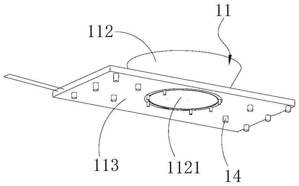
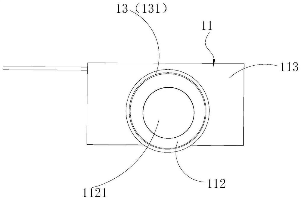
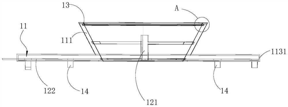
The invention relates to a drying device and electrical equipment. The drying device comprises a shell and a jet flow part. The shell is arranged in a drying chamber and is provided with a gas inlet part for gas flow to pass through. The jet flow part is arranged on the shell, is configured to communicate with the gas inlet part and the drying chamber and is used for outputting the gas flow in the gas inlet part into gas jet flow sprayed towards the drying chamber. During drying operation, after external gas flow enters the gas inlet part, high-speed flowing gas jet flow is formed under the effect of the jet flow part, and the gas jet flow is jetted out through the jet flow part. At the moment, vacuum or negative pressure is formed in a certain area near the jet flow part under the effect of the gas jet flow, the gas flow in the drying chamber flows to the vacuum or negative pressure area in an accelerated mode under the disturbance of the gas jet flow, and therefore convection in the drying chamber is accelerated and strengthened, water stains on tableware can be taken away in an accelerated manner, and the drying efficiency is improved.

Description

technical field [0001] The present application relates to the technical field of household electrical appliances, in particular to a drying device and electrical equipment. Background technique [0002] Electrical equipment with a drying function, such as dishwashers, disinfection cabinets, cupboards, etc., generally dry the tableware in the drying room by slowly blowing hot air through holes in the wall of the drying room. In this drying method, the air velocity in the drying chamber is small so that the drying time is longer, which leads to low drying efficiency. Contents of the invention [0003] The present application aims at the problem of low drying efficiency of existing electrical equipment, and proposes a drying device and electrical equipment, which have the technical effect of high drying efficiency. [0004] A drying device, comprising: [0005] A casing disposed in the drying chamber, the casing has an air inlet for airflow to pass through; and [0006] Th...

Claims


Application Information

Patent Timeline
Patent Type & Authority Applications(China)
IPC IPC(8): F26B9/06F26B21/00F26B25/06A47L15/00
CPCF26B9/06F26B21/001F26B21/004F26B25/06A47L15/00
Inventor 周玮松王铭昭彭涛张雷霆陈茜鄢瀚
Owner GREE ELECTRIC APPLIANCES INC
Why Eureka
Try Eureka