Cosmetic raw material treatment equipment
A raw material processing and cosmetics technology, applied in grain processing, lighting and heating equipment, drying solid materials, etc., can solve the problems of low grinding efficiency and failure to form a good cooperative relationship between crushing and grinding, and achieve smooth powder output.
- Summary
- Abstract
- Description
- Claims
- Application Information
AI Technical Summary
Problems solved by technology
Method used
Image

Examples
specific Embodiment approach 1
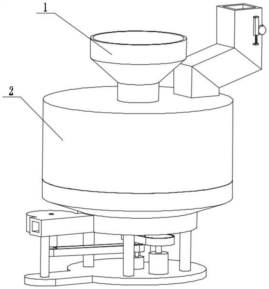
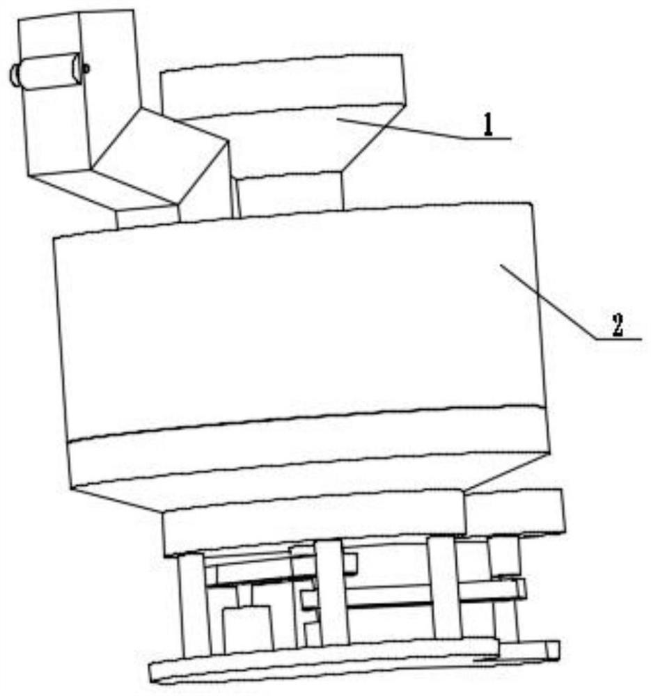
[0023] Combine below figure 1 , figure 2 , image 3 , Figure 4 , Figure 5 , Figure 6 , Figure 7 , Figure 8 , Figure 9 Describe this embodiment. The present invention relates to a cosmetic processing equipment, more specifically a cosmetic raw material processing equipment, including a processing actuator 1 and a fuselage mechanism 2. The equipment can be crushed, the equipment can feed and grind, and the equipment can quantify Given the amount of grinding, the equipment can produce powder smoothly.
[0024] The processing execution mechanism 1 is connected with the fuselage mechanism 2 .
specific Embodiment approach 2
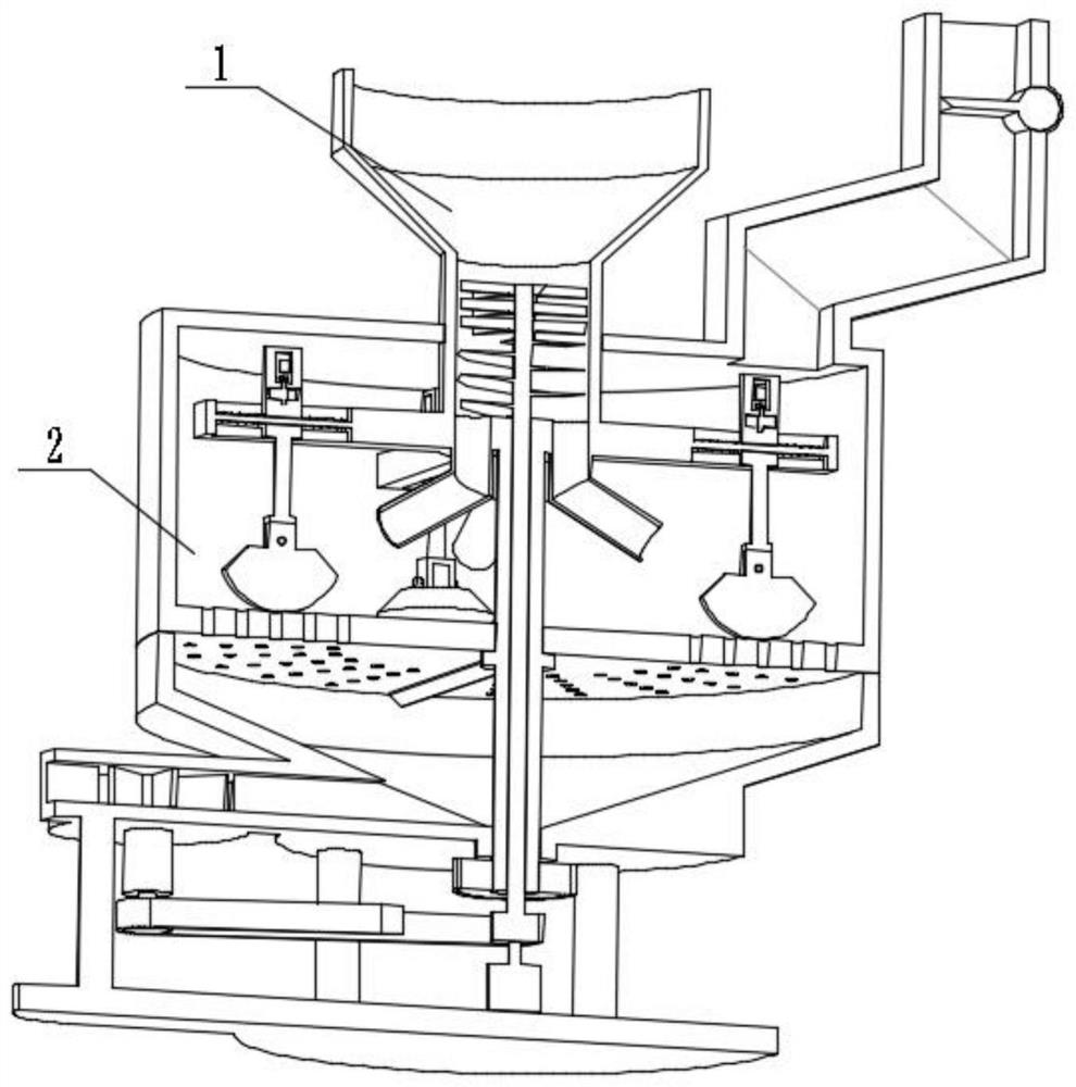
[0026] Combine below figure 1 , figure 2 , image 3 , Figure 4 , Figure 5 , Figure 6 , Figure 7 , Figure 8 , Figure 9Describe this embodiment, this embodiment will further explain Embodiment 1, and described processing actuator 1 comprises motor 1-1, belt 1-2, pulley 1-3, motor I1-4, pulley I1-5, belt I1 -6, pulley II1-7, wind wheel shaft 1-8, wind wheel 1-9, pulley III1-10, hollow shaft 1-11, scraper with bevel 1-12, grinding wheel 1-13, screw 1-14 , grinding arm 1-15, rotating arm 1-16, chute 1-17, sliding seat 1-18, belt shaft eccentric wheel 1-19, coupling 1-20, polarization motor 1-21, crushing bucket 1- 22. Crushing discharge pipe 1-23, crushing knife 1-24, screw shaft 1-25, light hole 1-26, limit rod 1-27, spring 1-28, long axis 1-29, motor 1-1 Connected with pulley 1-3, pulley 1-3 is frictionally connected with belt 1-2, motor I1-4 is connected with pulley I1-5, pulley I1-5 is frictionally connected with belt I1-6, belt I1-6 is connected with pulley II1...
specific Embodiment approach 3
[0028] Combine below figure 1 , figure 2 , image 3 , Figure 4 , Figure 5 , Figure 6 , Figure 7 , Figure 8 , Figure 9 Describe this embodiment, this embodiment will further explain the first embodiment, the fuselage mechanism 2 includes a base 2-1, a discharge port 2-2, a bellows 2-3, a collection box 2-4, and a casing 2 -5, bearing seat 2-6, feed pipe 2-7, feed port 2-8, limit plate 2-9, sliding rack 2-10, gear 2-11, limit square column 2-12, Spring 2-13, bearing seat I2-14, rotary gate with shaft 2-15, grinding plate 2-16, grinding hole 2-17, output channel 2-18, air cavity 2-19, bellows 2-3 and collection box 2-4 are all connected with the base 2-1, the bellows 2-3 is provided with a discharge port 2-2, the bellows 2-3 is connected and communicated with the collection box 2-4, the collection box 2-4 is connected with the casing 2- 5 are connected, and the casing 2-5 is provided with a bearing seat 2-6, and the bearing seat 2-6 is rotatably connected with the...
PUM
 Abstract
Description
Claims
Application Information
 - R&D Engineer
- R&D Manager
- IP Professional
- Industry Leading Data Capabilities
- Powerful AI technology
- Patent DNA Extraction
Browse by: Latest US Patents, China's latest patents, Technical Efficacy Thesaurus, Application Domain, Technology Topic.
© 2024 PatSnap. All rights reserved.Legal|Privacy policy|Modern Slavery Act Transparency Statement|Sitemap