A powder output device for laser additive equipment

A laser additive and equipment technology, applied in the direction of additive processing, process efficiency improvement, energy efficiency improvement, etc., can solve the problems of destroying the uniformity of the tiled powder layer, sticking, and low metal powder reserves, and achieves a reduction in the number of metal powders. Probability of small card death, quantitative and smooth powder output, and the effect of large powder storage capacity

Active Publication Date: 2022-05-17
NINGBO ZHONGWU DONGFANG OPTOELECTRONICS TECH CO LTD
View PDF8 Cites 0 Cited by
  • Summary
  • Abstract
  • Description
  • Claims
  • Application Information

AI Technical Summary

Problems solved by technology

[0003] Using this method to discharge powder, since the rotating roller is rotating, the inner wall of the container matched with the rotating roller is fixed. If the gap between the rotating roller and the inner wall of the container is large, the metal powder will leak and fall to the already flat surface. On the paved powder layer, the uniformity of the paved powder layer will be destroyed; if the gap between the roller and the inner wall of the container is small, there will be a large slip between the roller and the inner wall of the container during the rotation process Friction, especially when metal powder falls into the gap, the larger sliding friction will directly cause the jamming of the roller; in addition, because the metal powder reserves in the ordinary roller are less, the roller needs to achieve a greater The speed of rotation is to quickly and stably discharge powder, and the acceleration of the rotation speed of the roller increases the probability of its jamming
[0004] Therefore, the existing laser additive equipment has the problem of easy powder leakage or sticking of the rotating roller.

Method used


Image

  • A powder output device for laser additive equipment
  • A powder output device for laser additive equipment
  • A powder output device for laser additive equipment

Examples


Embodiment

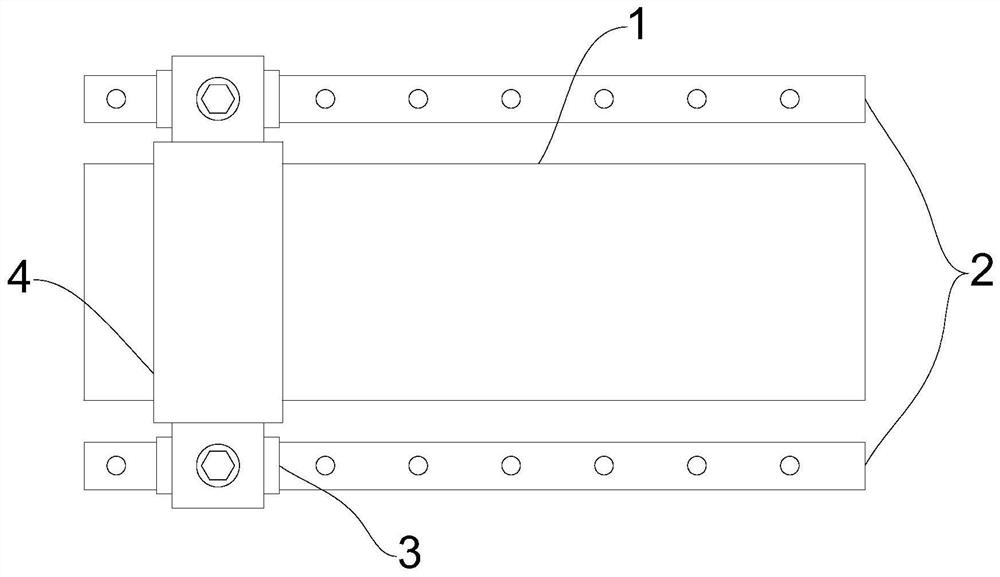
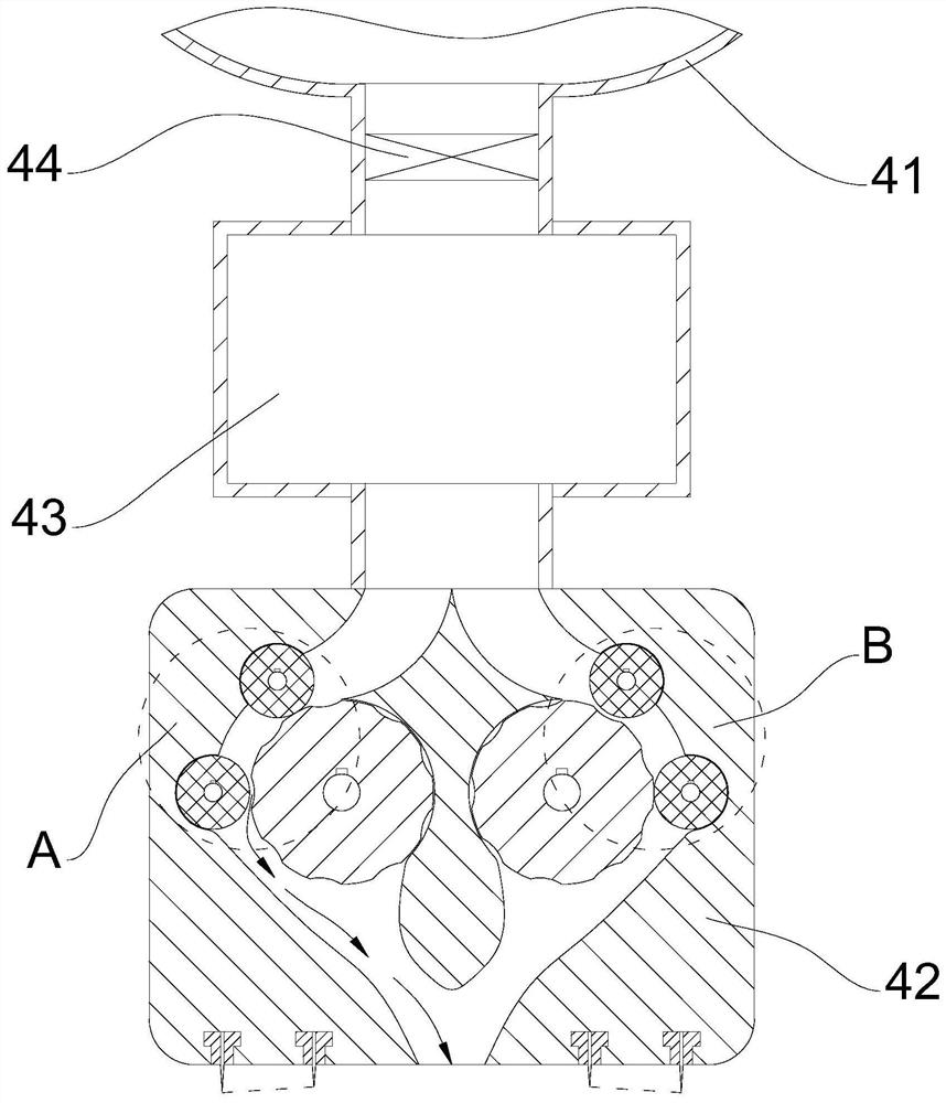
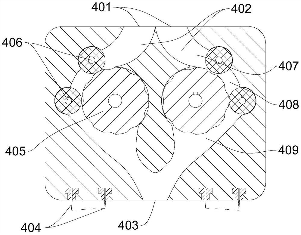
[0025] Embodiment: A powder output device of laser additive equipment, the structure is as follows Figure 1 to Figure 5 As shown, it includes a pair of guide rails 2, and the forming workpiece 1 is located between the guide rails 2 on both sides. 2, the powder outlet mechanism 4 is connected with a linear motor, and the linear motor is used to drive the powder outlet mechanism 4 to move back and forth on a straight line. The powder outlet mechanism 4 includes a storage funnel 41, and the volume of the storage funnel 41 can be stored for The metal powder processed by multiple parts, the storage hopper 41 is connected with a powder outlet module 42, and the powder outlet module 42 includes two powder inlets 401, two flow channels 402 and a powder outlet 403, two powder outlets The material inlet 401 is next to the docking material storage funnel 41 and has the same size, which can ensure the same feeding speed. The two flow channels 402 each correspond to a powder material inle...


PUM


Abstract

The invention discloses a powder outlet device of laser additive equipment, which includes a powder outlet mechanism, the powder outlet mechanism includes a storage hopper, and the powder outlet module is connected to the storage hopper, and the powder outlet module includes two powder outlet modules. A material inlet, two flow channels and a powder material outlet, each of the two flow channels corresponds to a powder material inlet and connects at the powder material outlet, and both sides of the powder material outlet are provided with scraping brush plates; The two flow channels are equipped with a powder outlet roller and a pair of guide rollers tangent to the outer cylindrical surface of the powder outlet roller. The pair of guide rollers divide the flow channel into an upper powder inlet section, a powder storage chamber and a lower powder outlet. The outer cylindrical surface of the powder outlet roller is provided with several grooves along the axial direction. With the rotation of the powder outlet roller, the powder storage chamber is alternately connected with the upper powder inlet section and the lower powder outlet section. The present invention has the advantages that the inner rollers are less prone to jamming and powder leakage, and can realize quantitative and smooth powder discharge.

Description

technical field [0001] The invention relates to the technical field of laser additive manufacturing, in particular to a powder discharge device of laser additive manufacturing equipment. Background technique [0002] Laser additive manufacturing technology is a method of using laser beam as heat source, heating materials to combine them, and directly manufacturing parts. It is called high-energy beam rapid manufacturing. It is an important branch in the field of additive manufacturing. Laser additive manufacturing of existing metal parts In the field of manufacturing, many equipment such as laser cladding, laser selective melting and other equipment need to use powder discharge devices. Laser cladding is one of them. Laser cladding uses high-energy laser beam irradiation to rapidly melt, expand and solidify. , cladding a layer of material with special physical, chemical or mechanical properties on the surface of the substrate to form a new composite material to make up for t...

Claims


Application Information

Patent Timeline
Patent Type & Authority Patents(China)
IPC IPC(8): B22F12/50B33Y30/00
CPCY02P10/25
Inventor 陈磊夏志新
Owner NINGBO ZHONGWU DONGFANG OPTOELECTRONICS TECH CO LTD
Why Eureka
Try Eureka