New application of electrophoretic overflow weir

An overflow weir, a new application technology, applied in electrophoretic plating, electrolytic coatings, coatings, etc., can solve the problems of liquid leakage, affecting the surface flow rate of electrophoresis tank liquid, too large gap between movable weir and fixed weir, etc. Surface flow rate to avoid the effect of uneven paint film

Active Publication Date: 2021-07-02
DESIGN INST NO 9 MINISTRY OF MECHINE BUILDING
View PDF3 Cites 0 Cited by
  • Summary
  • Abstract
  • Description
  • Claims
  • Application Information

AI Technical Summary

Problems solved by technology

[0005] Aiming at the deficiencies of the prior art, the present invention provides a new application of the electrophoresis overflow weir, which solves the problem that the gap between the movable weir and the fixed weir is too large to cause serious liquid leakage, thus affecting the surface flow velocity of the electrophoresis tank liquid

Method used


Image

  • New application of electrophoretic overflow weir
  • New application of electrophoretic overflow weir

Examples


Embodiment Construction

[0022] The following will clearly and completely describe the technical solutions in the embodiments of the present invention with reference to the accompanying drawings in the embodiments of the present invention. Obviously, the described embodiments are only some, not all, embodiments of the present invention. Based on the embodiments of the present invention, all other embodiments obtained by persons of ordinary skill in the art without making creative efforts belong to the protection scope of the present invention.

[0023] Example;:

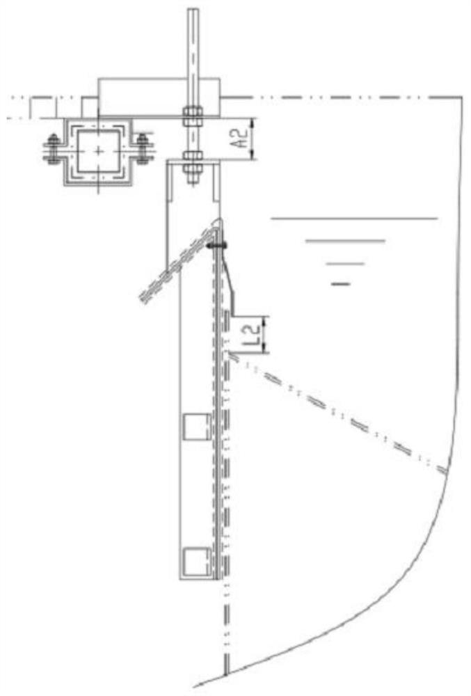
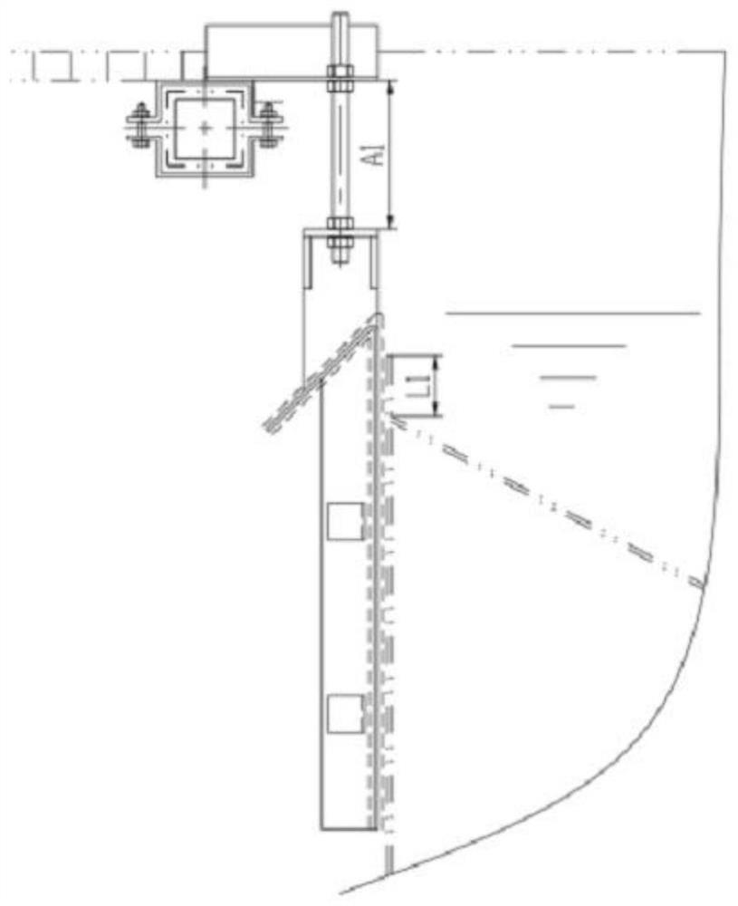
[0024] 2. If Figure 1-2 As shown, the embodiment of the present invention provides a new application of the electrophoretic overflow weir, including the following steps:

[0025] Step 1: Measure the height of the overflow weir and record it as L1 and measure the adjustment stroke A1 of the overflow weir;

[0026] Step 2: Select a suitable stainless steel baffle and measure the height L2 of the stainless steel plate, and fully consider the...


PUM

PropertyMeasurementUnit
widthaaaaaaaaaa

Abstract

The invention provides new application of an electrophoretic overflow weir and relates to the field of laying, supporting, connecting and overhauling of a pump liquid conveying pipeline. The new application of the electrophoretic overflow weir comprises the following steps that step1, the height of the overflow weir is measured and is recorded as L1, and the adjusting stroke A1 of the overflow weir is measured; step2, a proper stainless steel baffle is selected, the height L2 of the stainless steel plate is measured, and the direction size of the baffle is fully considered; and step3, one stainless steel baffle is additionally arranged in the width direction of a groove body of the movable overflow weir, the stainless steel baffle and the movable overflow weir are fixed through bolts, and position-limiting pins are driven into the stainless steel baffle. According to the new application of the electrophoretic overflow weir, one stainless steel plate is additionally arranged to serve as an important structure for adjusting the liquid level height of an electrophoretic tank and adjusting the surface flow speed, the situation that liquid leakage is serious due to the fact that a gap between one movable weir and one fixed weir is too large can be avoided after installation is completed, therefore, the surface flow speed of electrophoretic tank liquid will not be affected.

Description

technical field [0001] The invention relates to the fields of laying, supporting, connecting and overhauling pipelines for pumping liquid, in particular to the new application of electrophoretic overflow weirs. Background technique [0002] In the automobile painting production line, pretreatment and electrophoresis are the first process in the workshop, providing pretreatment work such as degreasing and iron powder removal for the body in white. The coating process has the advantages of full, uniform, smooth and smooth coating. The hardness, adhesion, corrosion resistance, impact performance and permeability of the electrophoretic paint film are obviously superior to other coating processes. [0003] However, the structure of the overflow weir of the electrophoresis tank is an important structure for adjusting the liquid level of the electrophoresis tank and adjusting the surface velocity. Generally, after the installation is completed, the gap between the movable weir and ...

Claims


Application Information

Patent Timeline
Patent Type & Authority Applications(China)
IPC IPC(8): C25D13/12C25D13/22
CPCC25D13/12C25D13/22
Inventor 潘成功
Owner DESIGN INST NO 9 MINISTRY OF MECHINE BUILDING
Why Eureka
Try Eureka