Self-supporting shadow-free LED lamp filament and LED lamp
A technology for LED filaments and LED lamps, which is applied to semiconductor devices of light-emitting elements, lighting devices, light sources, etc., and can solve problems such as filaments forming shadows
- Summary
- Abstract
- Description
- Claims
- Application Information
AI Technical Summary
Problems solved by technology
Method used
Image
Examples
Embodiment 1
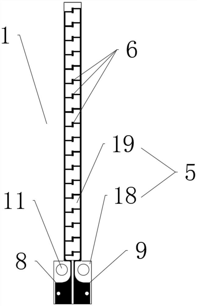
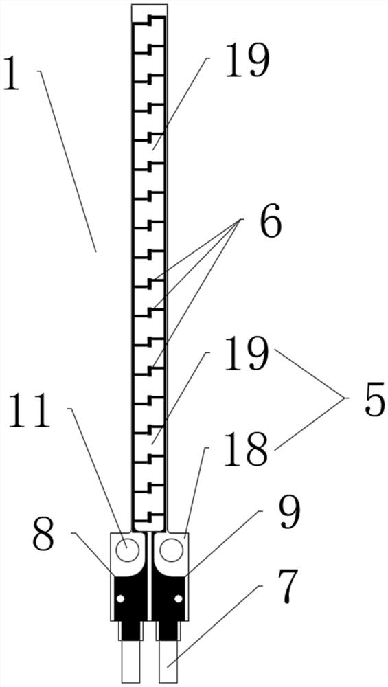
[0041] refer to figure 1 , the present embodiment provides a self-supporting LED filament without shadow, and the LED filament includes a transparent PCB board 5, a plurality of LED chips 6 located on the PCB board 5 and covering the PCB board 5 and the LED chips 6 Fluorescent glue on the periphery.
[0042] The PCB board 5 has two parts, the first area 18 and the second area 19, and the width of the first area 18 is greater than the width of the second area 19, the first area 18 is inserted into the lamp holder 3 of the LED lamp, And it is fixedly connected with the lamp holder 3 , the LED chip 6 is disposed on the side of the second area 19 , and the first pad 8 and the second pad 9 are disposed on the first area 18 . The first pad 8 and the second pad 9 serve as the input end and the output end of the LED filament respectively, and are connected to the power supply through the positive line and the negative line. Since the first welding pad 8 and the second welding pad 9 ...
Embodiment 2
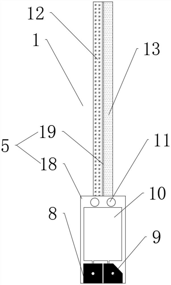
[0051] refer to image 3 , the present embodiment provides a self-supporting LED filament without shadow, including a transparent PCB board 5 , a plurality of LED chips 6 mounted on the PCB board and a control circuit 10 .
[0052] The PCB board 5 has two parts, the first area 18 and the second area 19, and the width of the first area 18 is greater than the width of the second area 19, the first area 18 is inserted into the lamp holder 3 of the LED lamp, And it is fixedly connected with the lamp holder 3, the LED chip 6 is arranged on the side of the second area 19, the control circuit 10 is arranged on the side of the first area 18, and the first area 18 is provided with The first pad 8 and the second pad 9 .
[0053] The first area 18 and the second area 19 have conductive patterns, and the LED chip 6 is electrically connected to the circuit inside the lamp holder 3 through the conductive patterns.
[0054] In addition, a plurality of LED chips 6 are evenly arranged in a m...
Embodiment 3
[0060] refer to Figure 4 , the present embodiment provides a self-supporting LED filament without shadow, including a transparent PCB board 5 , a plurality of LED chips 6 mounted on the PCB board and a control circuit 10 .
[0061] The PCB board 5 has two parts, the first area 18 and the second area 19, and the width of the first area 18 is greater than the width of the second area 19, the first area 18 is inserted into the lamp holder 3 of the LED lamp, And it is fixedly connected with the lamp holder 3, the LED chip 6 is arranged on the side of the second area 19, the control circuit 10 is arranged on the side of the first area 18, and the first area 18 is provided with The first pad 8 and the second pad 9 . Since the width of the first area 18 is greater than the width of the second area 19, after the first area 18 is installed in the lamp holder 3 of the LED lamp, the self-support of the PCB board 5 is more firm, and the connection between the first area 18 and the secon...
PUM
| Property | Measurement | Unit |
|---|---|---|
| thickness | aaaaa | aaaaa |
Abstract
Description
Claims
Application Information
 - R&D
- Intellectual Property
- Life Sciences
- Materials
- Tech Scout
- Unparalleled Data Quality
- Higher Quality Content
- 60% Fewer Hallucinations
Browse by: Latest US Patents, China's latest patents, Technical Efficacy Thesaurus, Application Domain, Technology Topic, Popular Technical Reports.
© 2025 PatSnap. All rights reserved.Legal|Privacy policy|Modern Slavery Act Transparency Statement|Sitemap|About US| Contact US: help@patsnap.com


