
Device for collecting equipment parts

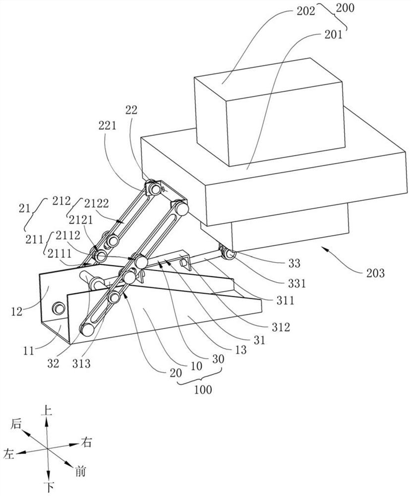
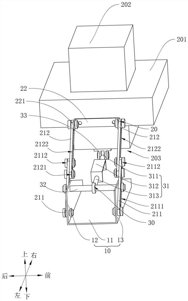
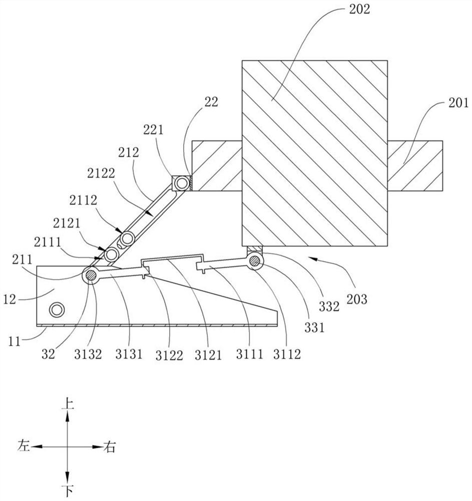
A technology for collecting equipment and parts, applied in the directions of feeding devices, positioning devices, storage devices, etc., can solve the problems of inconvenient collection of parts and low collection efficiency, and achieve the effect of high collection efficiency and convenient and fast collection of parts

Active Publication Date: 2021-07-09
ANHUI JIANGHUAI AUTOMOBILE GRP CORP LTD
View PDF4 Cites 0 Cited by
  • Summary
  • Abstract
  • Description
  • Claims
  • Application Information

AI Technical Summary

Problems solved by technology

[0003] The main purpose of this invention is to propose a device for collecting equipment parts, aiming to solve the problem of inconvenient and low collection efficiency of parts collection

Method used


Image

  • Device for collecting equipment parts
  • Device for collecting equipment parts
  • Device for collecting equipment parts

Examples


Embodiment Construction

[0027] The technical solutions in this embodiment will be clearly and completely described below in conjunction with the accompanying drawings in this embodiment. Obviously, the described embodiments are only part of the embodiments of the present invention, not all of them. Based on the embodiments of the present invention, all other embodiments obtained by persons of ordinary skill in the art without creative efforts fall within the protection scope of the present invention.

[0028] It should be noted that all directional indications (such as up, down, left, right, front, back...) in this embodiment are only used to explain the relative relationship between the various components in a certain posture (as shown in the figure). When the positional relationship, movement conditions, etc., if the specific posture changes, the directional indication will also change accordingly.

[0029] In addition, in the present invention, descriptions such as "first", "second" and so on are ...


PUM


Abstract

The invention discloses a device for collecting equipment parts. Equipment comprises a fixed part and a lifting part which ascends and descends relative to the fixed part; the device for collecting the equipment parts comprises a receiving hopper, a connecting assembly and a push-pull mechanism, wherein one end of the connecting assembly is hinged to the fixed part, and the other end of the connecting assembly is fixed to the receiving hopper; the push-pull mechanism comprises a push-pull assembly and a first connecting shaft, the first connecting shaft is fixed to the position, close to the receiving hopper, of the connecting assembly, one end of the push-pull assembly is hinged to the first connecting shaft, and the other end of the push-pull assembly is hinged to the lifting part; the lifting part is used for driving the push-pull assembly to descend or ascend, so that the push-pull assembly pushes and pulls the connecting assembly through the first connecting shaft, the connecting assembly correspondingly drives the receiving hopper to reciprocate between the initial position and the receiving position, and the receiving hopper can collect the equipment parts when moving to the receiving position; and the device can finish part collection along with ascending of the lifting part relative to the fixed part, and has the advantages of being convenient and rapid in part collection and high in collection efficiency.

Description

technical field [0001] The invention relates to the technical field of mechanical manufacturing, in particular to a device for collecting equipment parts. Background technique [0002] At present, stamping parts are generally made by stamping dies. First, the workpiece to be processed is placed between the upper die and the lower die of the die, and the upper die of the die is lowered relative to the lower die, so that the upper die and the lower die are closed to complete the workpiece. Blanking, drawing, trimming, flanging and other processes, and then complete the blanking to obtain qualified stamping parts. After the processing is completed, the upper mold of the mold will rise relative to the lower mold to open the upper mold and the lower mold. Some stamped parts that have been processed will fall to the lower die after going up a certain distance with the upper die. It is necessary to manually pick up the stamped parts that fell on the lower die and put them into the ...

Claims


Application Information

Patent Timeline
IPC IPC(8): B21D43/20
CPCB21D43/20
Inventor 刘春雨郑薇柴克文李月伟刘睿希
Owner ANHUI JIANGHUAI AUTOMOBILE GRP CORP LTD
Learn More