Unbonded steel strand oil removal device

A steel strand, unbonded technology, applied in the field of unbonded steel strand degreasing devices, can solve the problems of poor cleaning effect, scratches by workers, oil stains on the surface of steel strands and stubborn debris residues, etc.

A steel strand, unbonded technology, applied in the field of unbonded steel strand degreasing devices, can solve the problems of poor cleaning effect, scratches by workers, oil stains on the surface of steel strands and stubborn debris residues, etc.

CN113089350AActive Publication Date: 2021-07-09CHINA CONSTR FIFTH ENG DIV CORP LTD +1

Image

  • Unbonded steel strand oil removal device
  • Unbonded steel strand oil removal device
  • Unbonded steel strand oil removal device

Examples


Embodiment Construction

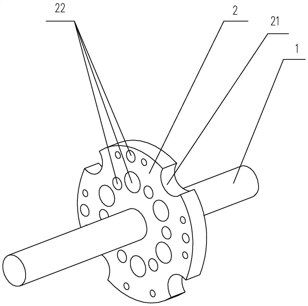
[0024] The first embodiment of the unbonded steel strand degreasing device of the present invention is as figure 1 As shown: it includes a support piece 1 and a work piece 2, the work piece 2 is arranged on the support piece 1, and several groups of snap-in grooves are evenly distributed on the work piece 2, and each set of snap-in grooves includes a number of different sizes. A slot hole 22 arranged on the work piece 2 and an arc-shaped groove 21 arranged on the edge of the work piece 2 .

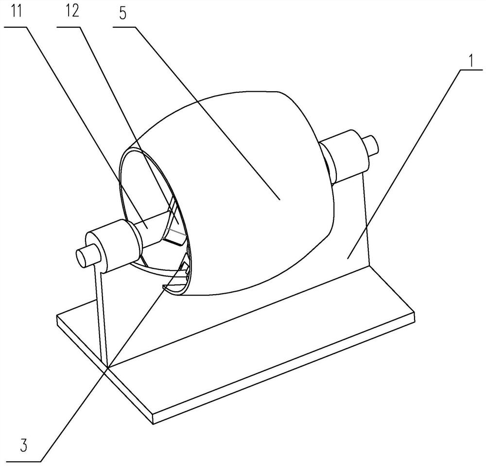
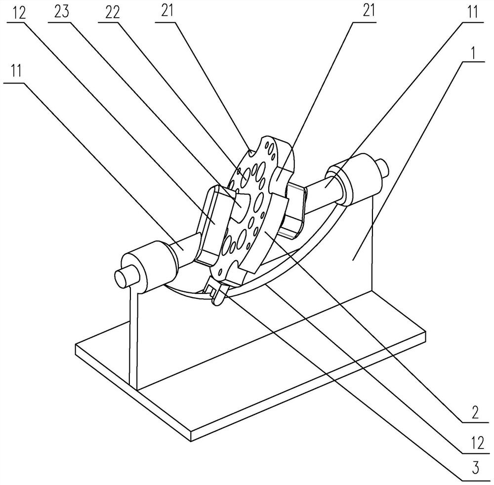
[0025] The second embodiment of the unbonded steel strand degreasing device of the present invention is as figure 2 and image 3 As shown: it includes a support piece 1 and a work piece 2, the work piece 2 is arranged on the support piece 1, and several groups of snap-in grooves are evenly distributed on the work piece 2, and each set of snap-in grooves includes a number of different sizes. A slot hole 22 arranged on the work piece 2 and an arc-shaped groove 21 arranged on the edge of t...


PUM


Abstract

The invention discloses an unbonded steel strand oil removing device which comprises a supporting piece and a working piece, wherein the working piece is arranged on the supporting piece, a plurality of sets of clamping grooves are evenly distributed in the working piece, and each set of clamping grooves comprises a plurality of groove holes which are different in size and formed in the working piece and an arc-shaped groove formed in the edge of the working piece. Oil stains and stubborn chippings on the surface of a steel strand can be efficiently removed, and meanwhile the structure is simple.

Description

technical field [0001] The invention relates to the technical field of civil engineering, in particular to an unbonded steel strand degreasing device. Background technique [0002] As we all know, before the steel strand is stranded, because there are many oil stains on the surface and the skin debris produced by the tensile deformation of the steel strand, it is necessary to clean the surface of the steel strand. Wipe the surface of the steel strand in the transmission state. The cleaning effect of this method is poor. There are more oil stains and stubborn debris on the surface of the steel strand. scrape. Contents of the invention [0003] Aiming at the deficiencies of the prior art, the present invention provides a degreasing device for unbonded steel strands, which can efficiently remove oil stains and stubborn debris on the surface of steel strands, and meanwhile has a simple structure. [0004] In order to achieve the above object, the present invention provides a...

Claims


Application Information

Patent Timeline
09 Jul 2021
Publication
CN113089350A
IPC
D07B1/06; D07B5/00; D07B7/02; D07B7/16; B08B1/00; B08B1/02; B08B13/00
CPC
D07B1/0673; D07B5/00; D07B7/16; D07B7/02; B08B13/00; D07B2201/2001; B08B2220/01; B08B1/10
Inventors
肖豹; 蒋春桂