Concealed drainer for building

A hidden, building technology, applied in the direction of buildings, drainage structures, water supply devices, etc., can solve the problems of reduced drainage efficiency, low drainage efficiency, and high installation requirements, and achieve high drainage efficiency, large water intake area, and large installation area. Effect

Inactive Publication Date: 2021-07-09
苏利娟
View PDF5 Cites 2 Cited by
  • Summary
  • Abstract
  • Description
  • Claims
  • Application Information

AI Technical Summary

Problems solved by technology

However, people's quality of life is improving nowadays, and the shower is a pressurized shower with a large flow rate, and the water output per unit time is even larger. The floor drain with this traditional structure is blocked by hair due to the mesh size of the filter. , resulting in a lower water launch efficiency; at the same time, due to the small number of water holes on the surface, the water launch efficiency is further reduced
Therefore, during the bathing process, water can be found to accumulate in the wet area, causing situations where people fall
At the same time, this traditional sinking floor drain has high installation requirements during installation; a slight height deviation will lead to water accumulation

Method used


Image

  • Concealed drainer for building
  • Concealed drainer for building
  • Concealed drainer for building

Examples


Embodiment 1

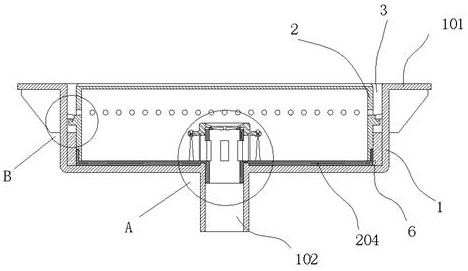
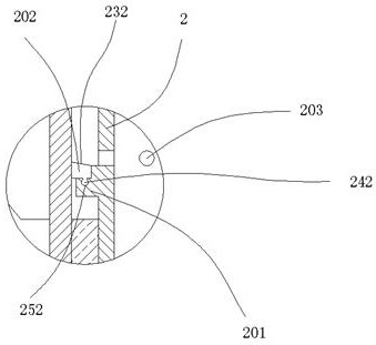
[0032] A building concealed sewer, comprising a built-in box body 1, the upper end of the box body 1 has an opening, the top edge of the box body 1 is provided with an outer edge part 101, the box body 1 A sewer nozzle 102 is provided at the bottom of the box body, an inner box body 2 is provided inside the box body 1, and a flange part 201 is provided on the outer wall of the box body 2, and the upper part of the flange part 201 is assembled There is a sealing strip 202, the sealing strip 202 forms a seal with the inner wall of the box body 1 after contacting it, and a water inlet hole 203 is arranged on the outer wall of the inner box body 2 above the flange part 201; A water gap 3 is formed between the box body 1 and the inner box body 2; a detachable box cover 204 is provided at the bottom of the inner box body 2; Water inlet pipe 205; the lower end of the water inlet pipe 205 is inserted downward into the mouth of the water pipe 102; the outer wall of the water inlet pipe...

Embodiment 2

[0034] The inner bottom position of the box body 1 is provided with an upward convex collar 121; the bottom of the box cover 204 is provided with an annular groove 222 embedded in the collar 121; the above structure is to realize the box body 1 and the inner box The alignment installation of the body 2 ensures that the distance between the outer wall of the flange part 201 and the inner wall of the box body 1 is uniform; it is convenient to seal through the sealing strip 202 later.

Embodiment 3

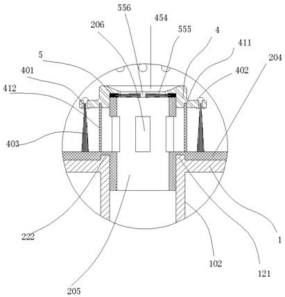
[0036]An annular slot 411 is arranged at the bottom position of the end cover 4, and a filter screen 412 is inserted in the annular slot 411, and the filter screen 412 is located inside the steel wire bristles 403; two adjacent bundles of steel wires A water gap is formed between the tops of the bristles 403; the setting of the filter screen 412 is to increase the drainage when the water level of the inner box body 2 rises to the water gap. Under normal conditions, the water is filtered and intercepted by the steel wire bristles 403. However, when the amount of water is large and the water penetration efficiency of the steel wire bristles 403 is insufficient, it can pass through the steel wire bristles 403 and filter through the filter screen 412; increase the water discharge rate, and at the same time Increase the filtering effect on the sewer; reduce the chance of the sewer pipe being blocked by hair.


PUM


Abstract

The building hidden drainer comprises an embedded box body, an opening is formed in the upper end of the box body, an outer edge part is arranged at the extending edge of the top of the box body, a sewer pipe opening is formed in the bottom of the box body, an inner box body is arranged in the box body, and a water outlet is formed in the inner box body. A convex edge part is arranged on the outer wall of the box body, a sealing strip is assembled at the upper part of the convex edge part, the sealing strip is in contact with the inner wall of the box body to form sealing with the inner wall of the box body, and a water inlet hole is formed in the outer wall of the inner box body and above the convex edge part. A water draining gap is formed between the box body and the inner box body. The device is larger in launching area and higher in launching efficiency, and meanwhile, the mounting difficulty is reduced.

Description

technical field [0001] The invention relates to a building concealed drain device. Background technique [0002] In the bathroom with wet and dry separation, the floor drain in the wet area is the only drainage location. [0003] In the prior art, the water is launched through a plurality of drainage holes on the surface of the floor drain. After the water is launched, the water is filtered through the built-in filter of the floor drain, and then discharged downward into the sewer pipe; , it can meet the needs of launching. However, people's quality of life is improving nowadays, and the shower is a pressurized shower with a large flow rate, and the water output per unit time is even larger. The floor drain with this traditional structure is blocked by hair due to the mesh size of the filter. , resulting in a lower water launch efficiency; at the same time, due to the small number of water holes on the surface, the water launch efficiency is further reduced. Therefore, du...

Claims


Application Information

Patent Timeline
Patent Type & Authority Applications(China)
IPC IPC(8): E03F5/04E03F5/14
CPCE03F5/0407E03F5/14
Inventor 苏利娟
Owner 苏利娟
Why Eureka
Try Eureka