Dynamic pipeline arrangement method

A layout method and pipeline technology, applied in the direction of hoses, pipes, pipe supports, etc., can solve the problems of pipeline winding, twisting, scraping, etc., achieve smooth flow, ensure bending radius, and avoid twisting and bending

Active Publication Date: 2021-07-09
HUNAN WUXIN TUNNEL INTELLIGENT EQUIP CO LTD
View PDF8 Cites 0 Cited by
  • Summary
  • Abstract
  • Description
  • Claims
  • Application Information

AI Technical Summary

Problems solved by technology

[0004] The purpose of the present invention is to provide a dynamic pipeline layout method, which aims to solve the problems of the traditional pipeline layout method such as winding, twisting and scraping of the pipeline during the working process. The specific technical solution is as follows:

Method used


Image

  • Dynamic pipeline arrangement method
  • Dynamic pipeline arrangement method
  • Dynamic pipeline arrangement method

Examples


Embodiment 1

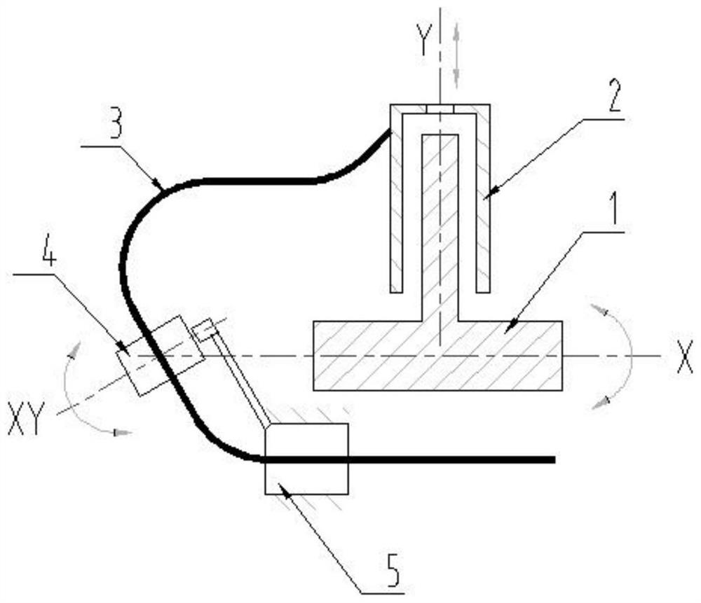
[0026] see figure 1 , a dynamic pipeline arrangement method, the pipeline 3 has a rotational movement around the rotational axis and a telescopic movement along a plane perpendicular to the rotational axis, wherein the telescopic structure 2 for the telescopic movement is arranged on the rotational structure 1 for the rotational movement, and the telescopic structure and the rotational movement The structures are all prior art, and the specific structural composition of the telescopic structure and the rotating structure will not be described in this embodiment. see figure 1 , the rotating structure 1 drives the pipeline 3 to rotate around the X axis (the X axis is the rotation axis), the telescopic structure drives the pipeline 3 to perform telescopic movement along the Y axis, and at least one point of the pipeline 3 is constrained by a pipe clamp, and the pipe clamp It is a fixed setting or a movable setting; the pipe clamp is set independently of the rotating structure 1 ...

Embodiment 2

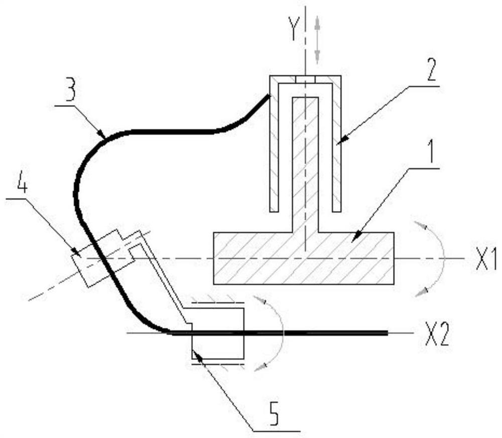
[0035] see figure 2 , the difference between this embodiment and Embodiment 1 is that the first pipe clamp 4 is fixedly arranged on the connector of the second pipe clamp 5, the second pipe clamp 5 is rotated, and the pipeline 3 drives the second pipe clamp 5 turn. Preferably, the axis of rotation of the second pipe clamp 5 is arranged parallel to the axis of rotation. It should be noted that setting the axis of rotation of the second pipe clamp parallel to the axis of rotation is only an optimal arrangement, and the rotation of the second pipe clamp The non-parallel setting of the axis and the rotation axis can also satisfy the requirement that the second pipe clamp rotates following the pipeline. see figure 2 , X1 in the figure is the axis of rotation, and X2 is the axis of rotation.

[0036] In this embodiment, the pipeline 3 directly drives the second pipe clamp 5 to rotate, and the first pipe clamp only serves to fix the pipeline.

Embodiment 3

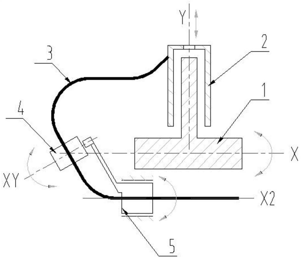
[0038] see image 3 , the difference between this embodiment and embodiment 1 is that the first pipe clamp 4 is rotatably arranged on the connector of the second pipe clamp 5, the second pipe clamp 5 is rotatably arranged, and the pipeline 3 drives the first pipe clamp 4 and the second pipe clamp 5 rotate. Preferably, the axis of rotation of the second pipe clamp 5 is arranged parallel to the axis of rotation. It should be noted that setting the axis of rotation of the second pipe clamp parallel to the axis of rotation is only an optimal arrangement, and the rotation of the second pipe clamp The non-parallel setting of the axis and the rotation axis can also satisfy the requirement that the second pipe clamp rotates following the pipeline. see image 3 , the X axis is the rotation axis of the rotating structure, X2 is the rotation axis of the second pipe clamp 5, and XY is the rotation axis of the first pipe clamp.

[0039]In this embodiment, the pipeline is constrained by ...


PUM


Abstract

The invention provides a dynamic pipeline arrangement method. A pipeline is subjected to rotating motion around a rotating axis and telescopic motion in the plane perpendicular to the rotating axis, a telescopic structure of telescopic motion is arranged on a rotating structure of rotating motion, and at least one point of the pipeline is restrained by pipe clamps. Each pipe clamp is fixedly arranged or movably arranged, and the pipe clamp is arranged independent of the rotating structure and the telescopic structure. The pipe clamps comprise the first pipe clamp and the second pipe clamp, and through the arrangement of the first pipe clamp and the second pipe clamp, the phenomenon that the pipeline is wound, twisted, scraped and the like in the rotating, stretching and retracting processes can be avoided. Moreover, the pipeline allowance generated by the telescopic motion can be controlled within the length range from the telescopic structure to the first pipe clamp. The pipeline can rotate along with the main body structure when the rotating structure rotates around the rotating axis, so that the pipeline is prevented from being twisted and bent, the reasonable bending radius of the pipeline is ensured, and a working medium in the pipeline can flow smoothly.

Description

technical field [0001] The invention relates to the technical field of pipeline layout, in particular to a dynamic pipeline layout method. Background technique [0002] In the prior art, the layout of static hydraulic pipelines is usually to arrange fixed pipe clamps along the trend of the internal working medium of the pipeline to achieve the purpose of pipeline fixation; the general layout of dynamic hydraulic pipelines often adopts the use of fixed pipe clamps to constrain the pipeline trend. The center of the active point or only the method of fixing the two ends of the pipeline is arranged. When the pipeline not only rotates around the axis but also has working conditions such as expansion and contraction along the plane of the vertical rotation axis, the traditional pipeline layout method will cause the pipeline to be entangled, twisted, scratched, etc. during the working process, affecting the pipeline. road life. [0003] To sum up, there is an urgent need for a dy...

Claims


Application Information

Patent Timeline
Patent Type & Authority Applications(China)
IPC IPC(8): F16L3/01F16L3/10F16L3/20F16L3/202
CPCF16L3/01F16L3/10F16L3/20F16L3/202
Inventor 龚俊宋祖源伍锡文
Owner HUNAN WUXIN TUNNEL INTELLIGENT EQUIP CO LTD
Why Eureka
Try Eureka