
Unloading method and unloading device for spherical hinge support of grid structure

A technology of spherical hinge support and grid structure, which is applied in building construction, construction, and building materials processing, etc., can solve problems such as the deformation and recovery of concrete columns that cannot be solved, and achieve the effect of improving unloading accuracy.

Pending Publication Date: 2021-07-16
CHINA CONSTR STEEL STRUCTURE CORP LTD +2
View PDF0 Cites 2 Cited by
  • Summary
  • Abstract
  • Description
  • Claims
  • Application Information

AI Technical Summary

Problems solved by technology

[0002] The connection between the long-span grid structure and the concrete column usually adopts spherical joint bearings. After the overall lifting of the long-span steel structure grid structure is completed, the grid structure needs to be unloaded. During the lifting process, the concrete column as the lifting point is prone to Larger displacement, in related technologies, it is usually used to build a temporary support tire frame, and set an adjustable support device on the temporary support tire frame, such as an hourglass device, to generate displacement in the unloading direction, so as to facilitate the unloading of the steel structure, and Remove the temporary support tire frame and hourglass device after unloading is completed. This unloading method is only suitable for temporary support systems with a large number of fixed-point supports, and cannot solve the problem of deformation recovery of concrete columns after lifting

Method used


Image

  • Unloading method and unloading device for spherical hinge support of grid structure
  • Unloading method and unloading device for spherical hinge support of grid structure
  • Unloading method and unloading device for spherical hinge support of grid structure

Examples


Embodiment Construction

[0031] Embodiments of the present invention are described in detail below, examples of which are shown in the drawings, wherein the same or similar reference numerals designate the same or similar elements or elements having the same or similar functions throughout. The embodiments described below by referring to the figures are exemplary only for explaining the present invention and should not be construed as limiting the present invention.

[0032] In the description of the present invention, it should be understood that the orientation descriptions, such as up, down, front, back, left, right, etc. indicated orientations or positional relationships are based on the orientations or positional relationships shown in the drawings, and are only In order to facilitate the description of the present invention and simplify the description, it does not indicate or imply that the device or element referred to must have a specific orientation, be constructed and operated in a specific ...


PUM


Abstract

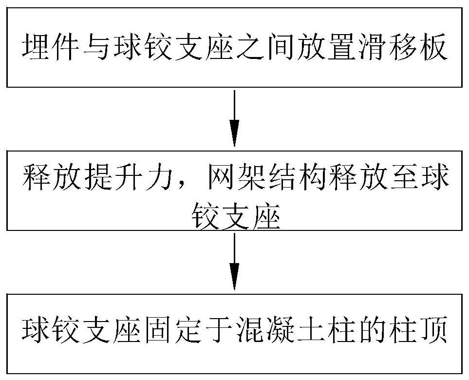
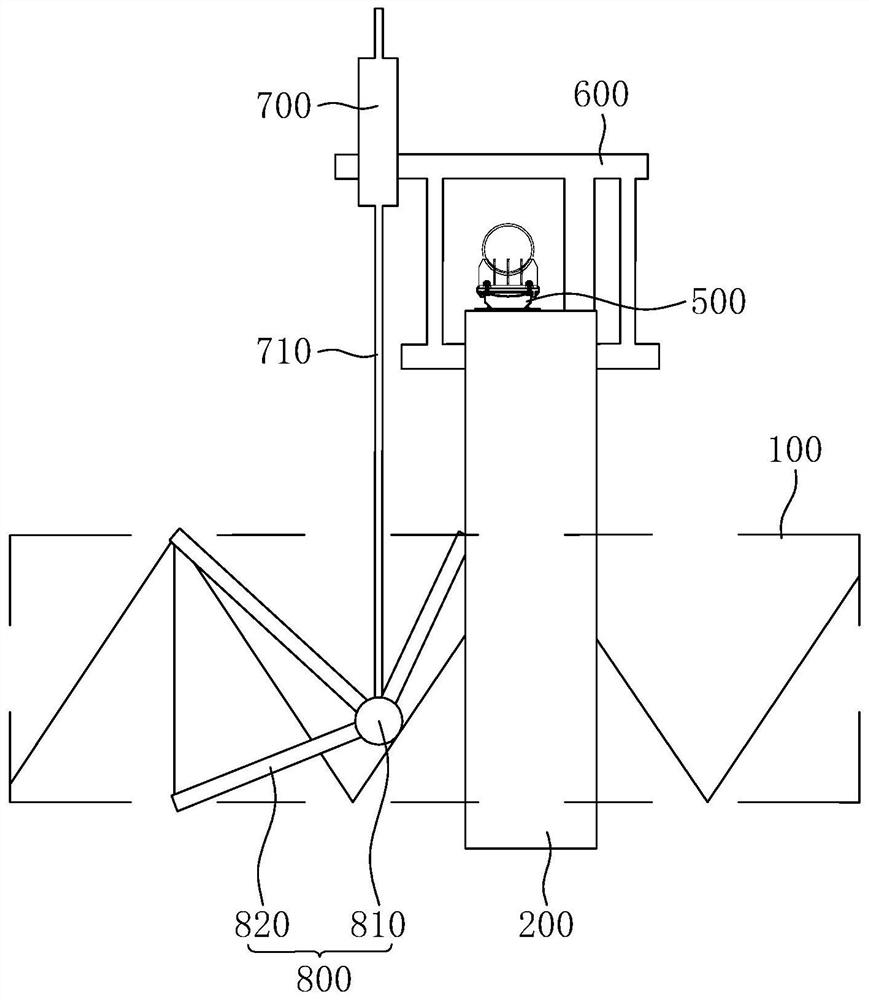
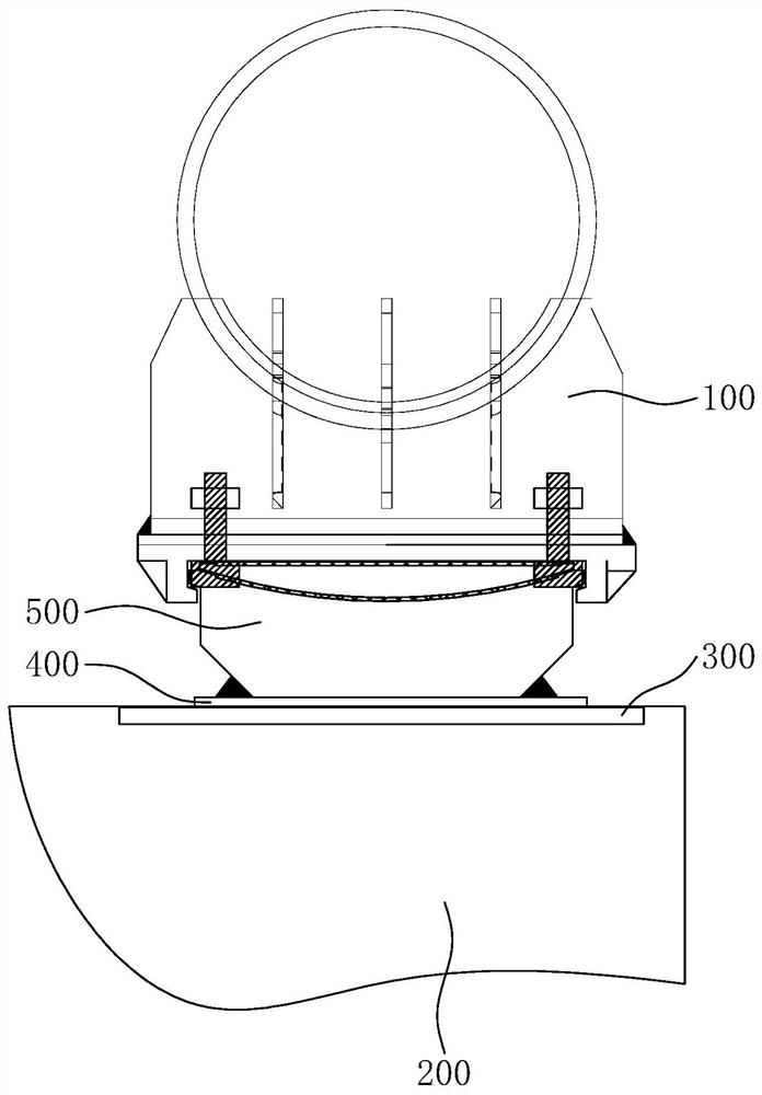
The invention discloses an unloading method and unloading device for a spherical hinge support of a grid structure. The unloading method and unloading device are used for deformation recovery of a concrete column. An embedded part and the spherical hinge support are arranged on the top of the concrete column, a sliding plate is placed between the embedded part and the spherical hinge support, lifting force on the grid structure is released, the grid structure is unloaded to the spherical hinge support, and the spherical hinge support is fixed to the column top of the concrete column. According to the unloading method and the unloading device for the spherical hinge support of the grid structure, the sliding plate is arranged between the embedded part at the top of the concrete column and the spherical hinge support, so that the friction force between the embedded part and the spherical hinge support is reduced, and the spherical hinge support can slide relative to the embedded part in the lifting force unloading process of the grid structure; therefore, deformation of the concrete column is recovered, the unloading precision of the grid structure is improved, and the supporting strength of the concrete column to the grid structure is improved.

Description

technical field [0001] The invention relates to the technical field of building construction, in particular to an unloading method and an unloading device for a spherical joint support of a grid structure. Background technique [0002] The connection between the long-span grid structure and the concrete column usually adopts spherical joint bearings. After the overall lifting of the long-span steel structure grid structure is completed, the grid structure needs to be unloaded. During the lifting process, the concrete column as the lifting point is prone to Larger displacement, in related technologies, it is usually used to build a temporary support tire frame, and set an adjustable support device on the temporary support tire frame, such as an hourglass device, to generate displacement in the unloading direction, so as to facilitate the unloading of the steel structure, and After the unloading is completed, the temporary support tire frame and the hourglass device are remove...

Claims


Application Information

Patent Timeline
IPC IPC(8): E04G21/14
CPCE04G21/14
Inventor 李梓轩邓德员陈振明胡从柱林强陈舟张伟雄马尹亮
Owner CHINA CONSTR STEEL STRUCTURE CORP LTD
Learn More