Supercharge Your Innovation With Domain-Expert AI Agents!

Flow stabilizing and pressurizing device of evaporator

A technology of supercharging device and evaporator, which is applied in the direction of modification using liquid cooling, cooling/ventilation/heating modification, electrical components, etc., which can solve the problem of affecting the use efficiency, unable to meet the needs of heat dissipation of high heat flux electronic components, disturbing water circulation and other issues

Pending Publication Date: 2021-07-16
LDC PRECISION ENG
View PDF0 Cites 0 Cited by
  • Summary
  • Abstract
  • Description
  • Claims
  • Application Information

AI Technical Summary

Problems solved by technology

The direct air cooling technology currently widely used can no longer meet the cooling needs of many electronic components with high heat flux, and other solutions must be sought
[0003] In the existing technology, in addition to the air cooling technology, it has the effect of using the liquid and gas state conversion of water to achieve heat dissipation. This technology provides two sets of heat spreaders and two sets of connected pipes, and one set of heat spreaders is used for evaporation. To take away the heat absorbed by the water, another set of heat spreaders is used to condense to cool down and return the output water for cooling and heat dissipation, and the pressures in the two sets of heat spreaders are different, so the water can be automatically transported back and forth into a cycle circuit, but there is a large amount of water circulation inside the heat spreader, so when the water flow path is not restricted, the internal water is prone to leakage, and the pressure cannot be properly retained inside, thus interfering with the flow of water The situation of internal circulation affects the use efficiency

Method used


Image

  • Flow stabilizing and pressurizing device of evaporator
  • Flow stabilizing and pressurizing device of evaporator
  • Flow stabilizing and pressurizing device of evaporator

Examples


no. 1 example

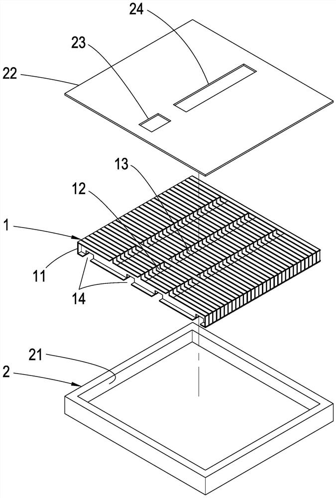
[0061] see Figure 1~Figure 2 , are respectively the three-dimensional schematic diagram of the steady-flow booster device of the evaporator of the present invention and the schematic cross-sectional view of the internal structure. As shown in the figure, it is the first embodiment of the overall structural configuration of the present invention, which at least includes a heat dissipation module 1 and a housing 2 ;

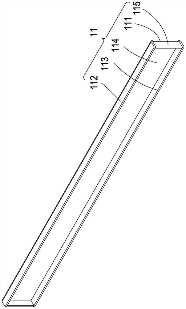
[0062]Wherein, the heat dissipation module 1 is formed by stacking and assembling a large number of heat dissipation components 11 continuously. . The second plate surface 112 and the third plate surface 113 are integrally formed or fixed to each other, so that a semi-open inner flow channel 114 is formed inside the heat dissipation assembly 11 . A fourth plate surface 115 is respectively provided at both ends, and a water inlet 12 and an air outlet 13 that are not connected to the outside are respectively opened on the heat dissipation module 1 (that is, some of...

no. 3 example

[0070] see Figure 11 , is the third embodiment of the overall structural configuration of the present invention. This embodiment continues the second embodiment. In this embodiment, there is a predetermined space between the two ends of each heat dissipation component 11 and the inner surface of the chamber 21, and each The blocking blocks 3 are arranged on the side of the outer cover 22 opposite to the chamber. When the outer cover 22 is closed on the chamber 21, each blocking block 3 is placed between the two ends of the heat dissipation assembly 11 and the chamber 21. between the inner sides, and each heat dissipation assembly 11 uses the half block form of the second to sixth embodiments (equivalent to Figure 8A , Figure 8B , Figure 8C , Figure 8D , Figure 8E , the second embodiment is used in the figure), and a gap 31 is opened at the two ends of the blocking block 3 relative to each inner flow channel 114, and the gap 31 maintains a space for liquid water or ga...

no. 5 example

[0072] see Figure 14 , Figure 15 , is the fifth embodiment of the overall structural configuration of the present invention. In this embodiment, there is a predetermined space between the two ends of each heat dissipation assembly 11 and the inner surface of the chamber 21, and each heat dissipation assembly 11 is used equivalent to Figure 8D In the half-block form of the fifth embodiment, the protruding section 116 can be located between the two ends of the heat dissipation assembly 11 and the inner surface of the housing chamber 21, and each fourth plate surface 115 is blocked on both sides of each inner flow channel 114. Above the end, the water inlet 12 is set at the position corresponding to the top of each protruding section 116, and the liquid water passes through the water inlet 23, the water inlet 12 in sequence, and enters the inner runners 114 through the bottom of each fourth plate surface 115 , and then circulate through each channel 14 to various places in th...


PUM


Abstract

The invention provides a flow stabilizing and pressurizing device of an evaporator. The device comprises a heat dissipation module and a shell, wherein the heat dissipation module is formed by continuously stacking and assembling a large number of heat dissipation assemblies, each heat dissipation assembly is provided with a first plate face, a second plate face and a third plate face so as to form a semi-open inner flow channel in the heat dissipation assembly, the two ends, opposite to the inner flow channel, of the heat dissipation assembly are each provided with a fourth plate face, the heat dissipation module is provided with a water inlet channel and an air outlet channel, and the heat dissipation module is arranged in the shell and an outer cover, so that the fourth plate faces can effectively block the two ends of the inner flow channel, vaporous water evaporated by heating in the inner flow channels can be effectively retained in the inner flow channels, and the internal pressure is quickly increased so as to stably and quickly discharge the vaporous water out of the air outlet channel.

Description

technical field [0001] The invention relates to a steady-flow booster device for an evaporator, which enables liquid water to undergo liquid-gas conversion inside to achieve a heat-dissipating structure, and is suitable for providing electronic components as heat-dissipating purposes. Background technique [0002] In recent years, the calorific value of electronic components has continued to increase rapidly with the improvement of semiconductor technology; how to improve the heat dissipation capacity of electronic components and maintain the normal operation of components has become a very important engineering topic. The direct air cooling technology widely used at present can no longer meet the heat dissipation requirements of many electronic components with high heat flux, and other solutions must be sought. [0003] In the existing technology, in addition to the air cooling technology, it has the effect of using the liquid and gas state conversion of water to achieve he...

Claims


Application Information

Patent Timeline
IPC IPC(8): H05K7/20
CPCH05K7/20309H05K7/20327
Inventor 徐启峰梁政仁陈志玮
Owner LDC PRECISION ENG
Features
  • R&D
  • Intellectual Property
  • Life Sciences
  • Materials
  • Tech Scout
  • Unparalleled Data Quality
  • Higher Quality Content
  • 60% Fewer Hallucinations
Learn More