Portable safe for fire arms and valuables
A portable technology for valuables, applied in safes, building structures, buildings, etc., to achieve the effects of solving hidden safety hazards, convenient loading and unloading, and novel and unique technical ideas
- Summary
- Abstract
- Description
- Claims
- Application Information
AI Technical Summary
Problems solved by technology
Method used
Image

Examples
Embodiment 1
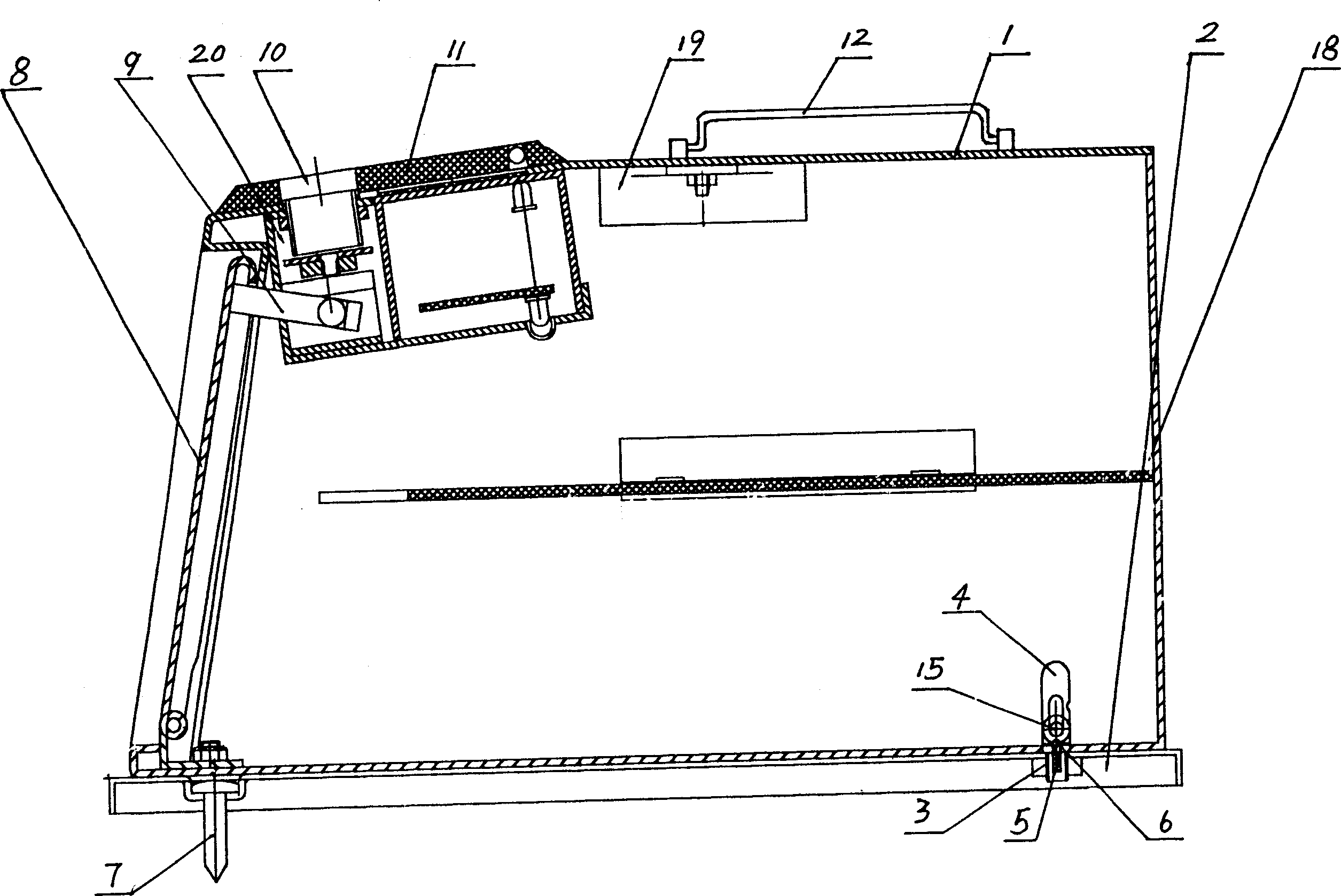
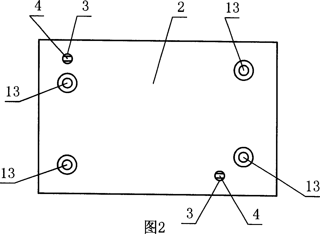
[0034] Embodiment one: see attached figure 1 ~accompanying drawing 4, a kind of portable pistol cabinet is made up of safe body 1, box door 8, control box 20, button panel 11, handle 12, dividing plate 18 and inner loading and unloading type fixed structure. Chamber door 8 is a door panel structure, and this door panel is hinged with the lower end of the casing 1 opening, and the hinge shaft is provided with a torsion spring that helps the door panel to open. The control box 20 includes an electronic combination lock and a mechanical lockset 10. The electronic combination lock controls two electromagnetic valves opposite to each other through the control circuit. Two hook bodies, the other end of deadbolt 9 is fixed on the door panel. The mechanical lock 10 acts on the mechanical working end of the solenoid valve through a cam mechanism. Chamber door 8 can be opened by mechanical lock 10 or electronic combination lock. The top of the casing 1 is provided with a key panel 11...
Embodiment 2
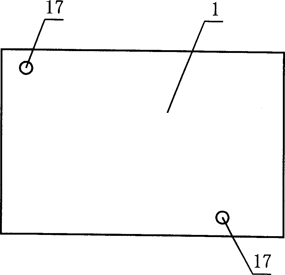
[0036] Embodiment 2: A portable pistol cabinet, which is composed of a safe body 1, a cabinet door 8, a control box 20, a key panel 11, a handle 12, a partition 18 and an internal loading and unloading fixed structure. The difference from the embodiment lies in the locking structure, see accompanying drawing 5, the locking structure is composed of a barb 21 arranged on the column pin 3, the barb 21 is connected in rotation around the column pin 3, the assembly hole 17 is connected with the barb The shape of the hook 21 matches. In order to make the positioning of the barb more reliable, the mounting hole 17 is provided with a positioning groove 24 for the barb 21 at the rotational position of the inner surface of the box body 1 , and a positioning spring 22 is provided axially between the column pin 3 and the barb 21 . Other structures are the same as in Embodiment 1.
PUM
 Abstract
Description
Claims
Application Information
 - R&D Engineer
- R&D Manager
- IP Professional
- Industry Leading Data Capabilities
- Powerful AI technology
- Patent DNA Extraction
Browse by: Latest US Patents, China's latest patents, Technical Efficacy Thesaurus, Application Domain, Technology Topic.
© 2024 PatSnap. All rights reserved.Legal|Privacy policy|Modern Slavery Act Transparency Statement|Sitemap