

Vacuum sewage conveying system for crossing obstacles
A technology for sewage transportation and obstacles, applied in the direction of cleaning hollow objects, cleaning methods and utensils, chemical instruments and methods, etc., can solve the problems of vacuum degree drop, pipeline blockage, etc., reduce pipeline blockage, shorten transportation distance, Avoid the effect of vacuum reduction
- Summary
- Abstract
- Description
- Claims
- Application Information
AI Technical Summary
Problems solved by technology
Method used
Image

Examples
Embodiment 1
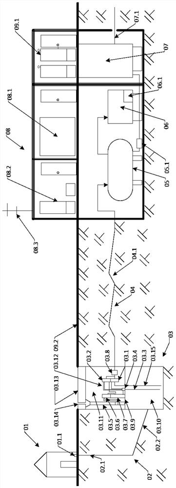
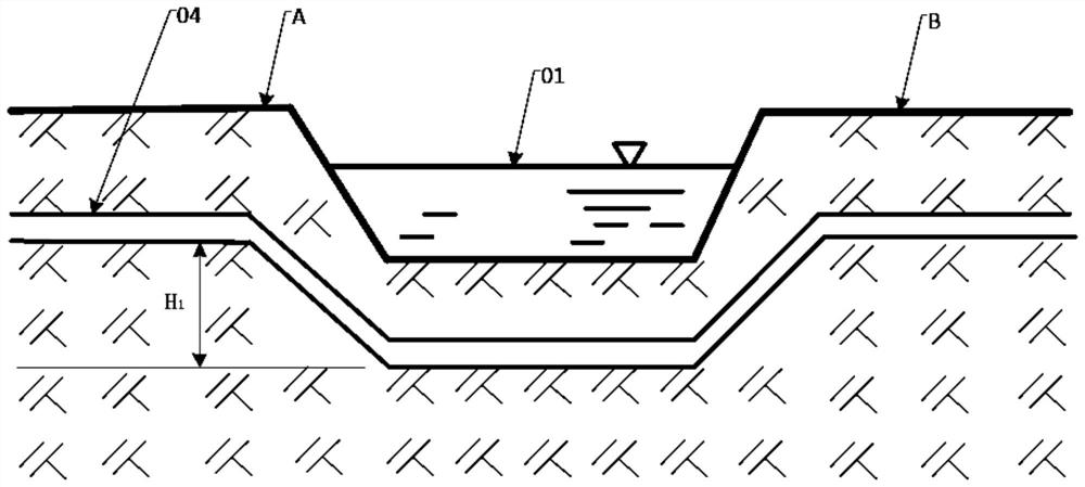
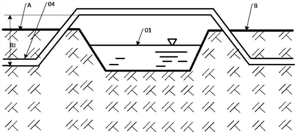
[0083] Such as Figure 5a , 5b As shown, a vacuum sewage conveying system for crossing obstacles, wherein the obstacles use trenches and buildings as application scenarios, but not limited to the above two scenarios, the system includes vacuum sewage pipelines passing through the obstacles (by Reference numerals are 04, 07, 08, 09, 10, the air pipeline 05 and the ventilation pipeline (the pipeline consisting of 12, 13, 14, 15) connected with the vacuum sewage pipeline road), respectively installed on the air pipeline 05 and the valve assembly on the ventilation pipeline (consisting of reference numerals 06, 16), and a controller 19 for controlling the action of the valve assembly; wherein one end of the air pipeline 05 is connected to the vacuum sewage The pipelines are connected, and the other end extends above the ground; the ventilation pipeline connects the upstream end and the downstream end of the vacuum sewage pipeline.
[0084]The vacuum sewage pipeline includes the ...
Embodiment 2
[0095] The difference between this embodiment and Embodiment 1 is that in Embodiment 1, the blowdown valve on the air pipeline 05 and the ventilation pipeline, and the controller 19 for switching on and off the controller 19 are all located below the ground in a sealed storage with waterproof, moisture-proof and freeze-proof functions. In the chamber 20; and in the present embodiment, as Figure 5c and 5d As shown, the blowdown valve on the air pipeline 05 and the ventilation pipeline (the pipeline formed by reference numerals 12, 13, 14, 15), and the controller 19 for controlling on-off are all located above the ground with waterproof, moisture-proof and freeze-proof In the sealed storage room 20 of the function; the former setting mode is convenient for passage, and the latter setting mode is convenient for disassembly and maintenance.
[0096] In the above two embodiments, the application scenarios of trenches and buildings are used, and no distinction will be made in the ...
Embodiment 3
[0099] Such as Figure 5e As shown, a vacuum sewage conveying system for crossing obstacles, including a vacuum sewage pipeline (composed of reference signs 04, 07, 08, 09, 10) passing through the obstacle, and a vacuum sewage pipeline The air pipeline 05 and the ventilation pipeline (composed of reference signs 21, 22, 23, 24), which are connected to the air pipeline 05, and the valve assembly respectively installed on the air pipeline 05 and the ventilation pipeline (represented by reference symbols 25, 26, 27, 28, 35), and a controller 19 for controlling the action of the valve assembly.
[0100] Among them, the vacuum sewage pipeline includes the sewage pipeline A04 connected in sequence along the sewage flow direction and arranged upstream, the sewage pipeline B07 that is close to the obstacle to the upstream side and bent downward, and the sewage pipeline installed below the obstacle C08, the sewage pipeline D09 that is bent toward the downstream side near the obstacle,...
PUM
 Abstract
Description
Claims
Application Information