Protective rope rolling and packaging device for new energy wind driven generator safety officer
A technology for wind turbines and safety guards, which is applied to the field of protective rope wrapping devices for new energy wind turbine safety guards, can solve the problems of low efficiency and large amount of operation, and achieves the purpose of preventing water immersion and dampness, improving efficiency, and shortening the usage time. effect of deadlines
- Summary
- Abstract
- Description
- Claims
- Application Information
AI Technical Summary
Problems solved by technology
Method used
Image
Examples
Embodiment 1
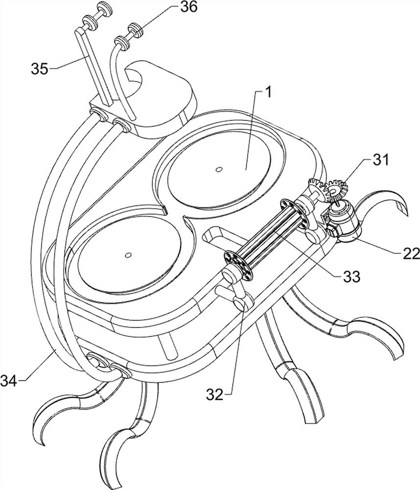
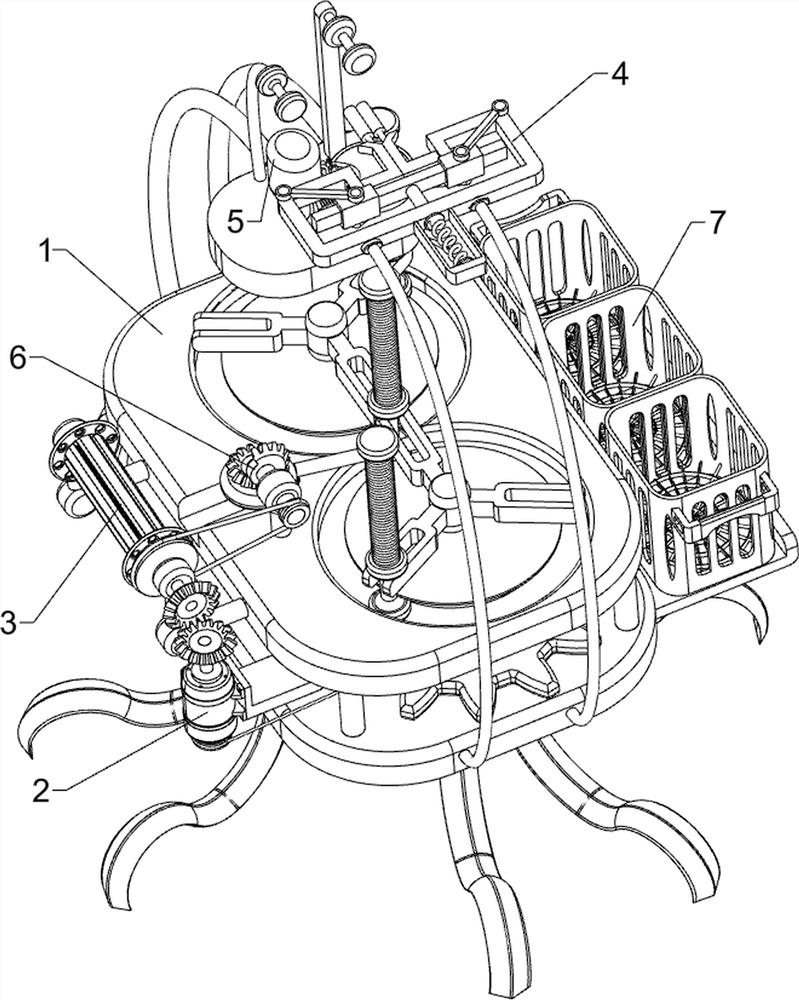
[0052] A protective rope rolling and packaging device for safety personnel of new energy wind power generators, such as figure 1 As shown, it includes a first fixed frame 1 , a weaving mechanism 2 and a rolling mechanism 3 , the top of the first fixed frame 1 is provided with a weaving mechanism 2 , and the upper front side of the first fixed frame 1 is connected with a rolling mechanism 3 .
[0053] The staff can place the synthetic fibers that need to be prepared in the weaving mechanism 2, and then start the weaving mechanism 2 to weave the synthetic fibers. At the same time, the operation of the weaving mechanism 2 drives the operation of the rolling mechanism 3 to wind up the braided rope, and all the weaving is completed. , stop the operation of the weaving mechanism 2 and collect the ropes.
Embodiment 2
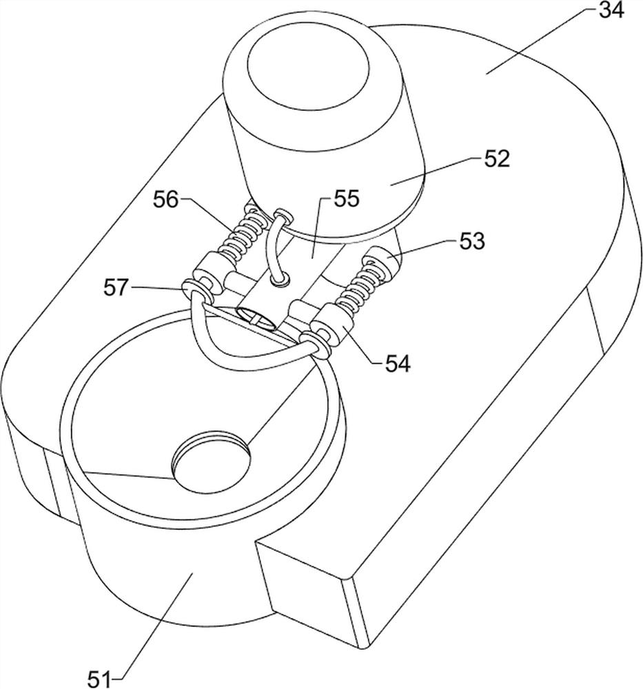
[0055] On the basis of Example 1, such as Figure 2 to Figure 4 As shown, the weaving mechanism 2 includes a support plate 21, a biaxial motor 22, a rotating shaft 23, a rotating clamp 24, a spur gear 25, a first transmission assembly 26 and a rope winding rod 27, and the right side of the first fixed frame 1 is connected with a support plate 21, a biaxial motor 22 is connected to the support plate 21, two rotating shafts 23 are connected in the middle of the first fixed frame 1 in a rotating manner, and the tops of the rotating shafts 23 are connected with rotating clips 24, and the rotating clips 24 are all located at the bottom of the first fixed frame 1. The top and the lower part of the rotating shaft 23 are connected with a spur gear 25, the spur gears 25 mesh with each other, the first transmission assembly 26 is connected between the right rotating shaft 23 and the lower output shaft of the biaxial motor 22, and the top of the first fixed frame 1 has a Horizontal 8-sha...
Embodiment 3
[0059] On the basis of Example 2, such as Figure 5 to Figure 8 As shown, a packaging mechanism 4 is also included, and the packaging mechanism 4 includes a second support frame 41, a second fixed frame 42, a first slide bar 43, a push rod 44, a first spring 45, a roll bar 46 and a second slide bar 47. The upper right side of the first fixed frame 1 is connected to the second support frame 41, the upper part of the second support frame 41 is connected to the second fixed frame 42, and the top left side of the second fixed frame 42 is connected to the first slide bar 43 in a symmetrical rotational manner , the inner wall of the right part of the second fixed frame 42 is slidably connected with a push rod 44, and the push rod 44 is slidably connected with the first sliding rod 43, and a first spring 45 is connected between the right side of the push rod 44 and the second fixed frame 42 The left part of the second fixed frame 42 is symmetrically slidably connected with a rolling ...
PUM
 Abstract
Description
Claims
Application Information
 - R&D
- Intellectual Property
- Life Sciences
- Materials
- Tech Scout
- Unparalleled Data Quality
- Higher Quality Content
- 60% Fewer Hallucinations
Browse by: Latest US Patents, China's latest patents, Technical Efficacy Thesaurus, Application Domain, Technology Topic, Popular Technical Reports.
© 2025 PatSnap. All rights reserved.Legal|Privacy policy|Modern Slavery Act Transparency Statement|Sitemap|About US| Contact US: help@patsnap.com


