Connecting device for lighting power supply of electric appliance, connecting assembly and refrigerator

A technology for connecting devices and lighting power supplies, which is applied to the components of lighting devices, lighting devices, fixed lighting devices, etc., which can solve the problems of easy damage to plug-in and pull-out mobile shelves, failure of electrical connections, etc., and achieve the goal of improving lighting experience Effect

Pending Publication Date: 2021-07-23
TYCO ELECTRONICS (SHANGHAI) CO LTD +1
View PDF0 Cites 0 Cited by
  • Summary
  • Abstract
  • Description
  • Claims
  • Application Information

AI Technical Summary

Problems solved by technology

In the prior art, due to the need to set electrical connectors on the mobile shelf, it is easy to be damaged when plugging and unplugging the mobile shelf, which will lead to failure of the electrical connection

Method used


Image

  • Connecting device for lighting power supply of electric appliance, connecting assembly and refrigerator
  • Connecting device for lighting power supply of electric appliance, connecting assembly and refrigerator
  • Connecting device for lighting power supply of electric appliance, connecting assembly and refrigerator

Examples


Embodiment 1

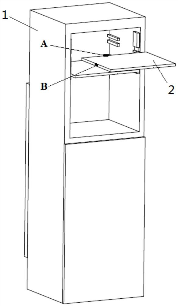
[0072] Such as figure 1 As shown, one or more shelves 2 of the refrigerator 1 are provided with lighting sources (for example, LED lights or LED light strips), and the connection assembly for the lighting power supply of electrical appliances disclosed by the present invention includes two kinds of connection devices, Wherein, the first connecting device is arranged on the inner wall of the refrigerator 1 , and the second connecting device is arranged on the corresponding shelf 2 . Such as figure 1 As shown, the first connecting device can be arranged on the inner rear wall of the refrigerator 1, and correspondingly, the second connecting device is arranged on the rear wall of the shelf 2 (such as figure 1 In the shown position A), when the shelf 2 is fully pushed into the refrigerator 1, the first connecting device is contacted and connected with the second connecting device, and the lighting power supply is connected. In addition, if figure 1 As shown, the first connectin...

Embodiment 2

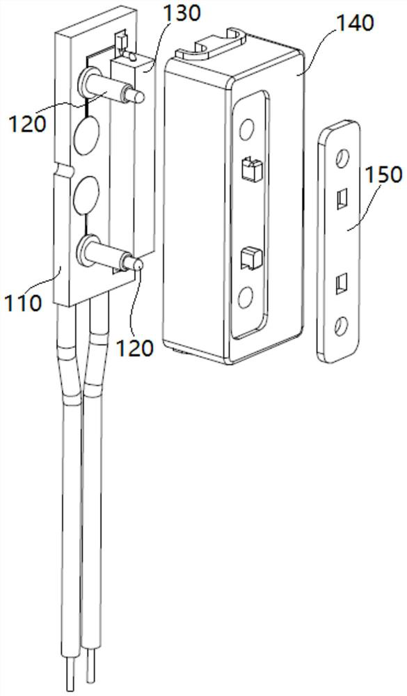
[0084] In this example, if Figure 5 , Image 6 As shown, it will be described in detail that the first connection device 100 is set in figure 1 The inner wall of the refrigerator 1, and the second connecting device 200 is set on figure 1 The case of the side walls of the shelf 2.

[0085] In this embodiment, the structure and principle of the first connecting device 100 are the same as those of the first connecting device 100 in Embodiment 1, which will not be repeated here.

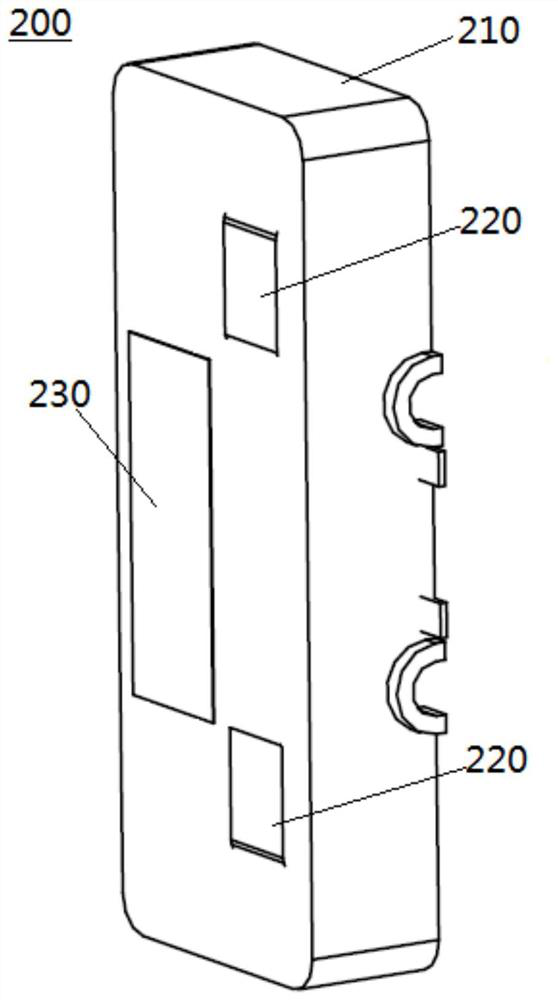
[0086] Such as Figure 5 As shown, in this embodiment, the second connection device 200 is arranged on the side wall of the shelf of the refrigerator, and includes: a second housing 210, at least one pair of metal contacts 220 and a magnet unit 230; wherein, the second The casing 210 is arranged on the shelf; at least one pair of metal contacts 220 is embedded in the second casing 210, and is arranged symmetrically with the at least one pair of elastic terminals 120 of the first connecting device 10...


PUM


Abstract

The invention discloses a connecting device for a lighting power supply of an electric appliance, a connecting assembly and a refrigerator. The connecting assembly for the lighting power source of the electric appliance comprises a first connecting device and a second connecting device, wherein the first connecting device comprises a first bottom plate installed on the inner wall of the electric appliance, at least one pair of elastic terminals arranged on the first bottom plate and an elastic sheet switch arranged on the first bottom plate, and when the elastic sheet switch is closed, and the at least one pair of elastic terminals is electrically connected with an external power supply for supplying power to the lighting power supply. According to the connecting device arranged on an inner wall of the electric appliance and the connecting device arranged on the shelf, the electric appliance can be electrically connected with the shelf, so the illumination light source arranged on the shelf is switched on. The scheme provided by the invention is simple, reliable and low in cost, and a purpose of illuminating the interior of the electric appliance by using the illuminating light source on the shelf can be achieved.

Description

technical field [0001] The disclosure relates to equipment lighting technology, and in particular to a connection device, a connection assembly and a refrigerator for a lighting power supply of an electrical appliance. Background technique [0002] Refrigerators and other similar devices currently on the market all adopt the top lighting method inside the device to realize the internal lighting of the device. For example, in the refrigerator, when there is too much food piled up, it is easy to block the light and affect the lighting effect. In order to improve user satisfaction, there is an urgent need for a better way to illuminate the interior of a device. [0003] In some electrical equipment, some lighting sources are installed on moving parts, for example, lighting lamps installed on a moving shelf of a refrigerator. In the prior art, an electrical connector needs to be arranged on the mobile shelf, and at the same time, a mating connector needs to be arranged on the ...

Claims


Application Information

Patent Timeline
Patent Type & Authority Applications(China)
IPC IPC(8): F21S8/00F21V23/04F21V23/06F21V21/002F21W131/305
CPCF21S8/00F21V23/06F21V21/002F21V23/04F21W2131/305
Inventor 潘磊卞卫峰坂井健P·R·拉金德拉
Owner TYCO ELECTRONICS (SHANGHAI) CO LTD
Why Eureka
Try Eureka