Tangential inclined ring film divergent cooling structure

A divergent cooling and inclined technology, which is applied to combustion engines, internal combustion piston engines, indirect carbon dioxide emission reduction, etc., can solve the problems of poor cooling of the wall surface, wall surface ablation, and limited cooling capacity, etc., to extend the cooling coverage time , to avoid ablation, to ensure the rationality of the effect

Active Publication Date: 2021-07-23
AECC HUNAN AVIATION POWERPLANT RES INST
View PDF22 Cites 3 Cited by
  • Summary
  • Abstract
  • Description
  • Claims
  • Application Information

AI Technical Summary

Problems solved by technology

[0004] The main disadvantages of the existing technical solutions: 1. The gas jet flow of the main combustion hole cuts off the cooling gas film covering the wall, and the local position downstream of the main combustion hole lacks a cooling gas film; 2. A low-velocity zone is usually formed downstream of the gas jet flow of the main combustion hole , the low-velocity area is generally a high-temperature area, which is likely to cause ablation of the wall surface; 3. If the main combustion hole uses an air intake bucket structure, the wall surface temperature of the bucket is usually high, and the existing cooling method cannot be used well 4. If divergent cooling holes are used downstream of the main combustion holes, the cooling capacity is usually limited, and the ablation problem cannot be solved well; in order to solve the above defects, a solution is now provided

Method used


Image

  • Tangential inclined ring film divergent cooling structure
  • Tangential inclined ring film divergent cooling structure
  • Tangential inclined ring film divergent cooling structure

Examples


Embodiment Construction

[0024] The technical solutions in the embodiments of the present invention will be clearly and completely described below in conjunction with the accompanying drawings in the embodiments of the present invention. Apparently, the described embodiments are only some of the embodiments of the present invention, not all of them. Based on the embodiments of the present invention, all other embodiments obtained by persons of ordinary skill in the art without making creative efforts all belong to the protection scope of the present invention.

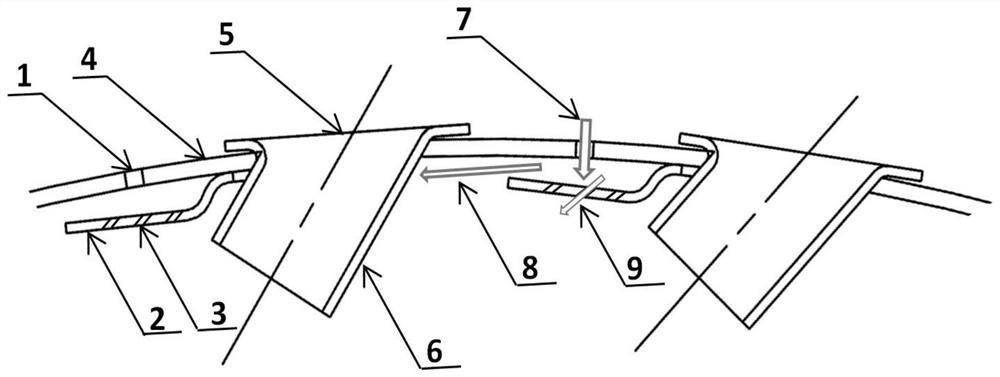
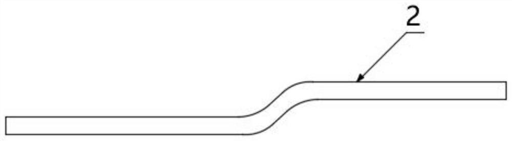
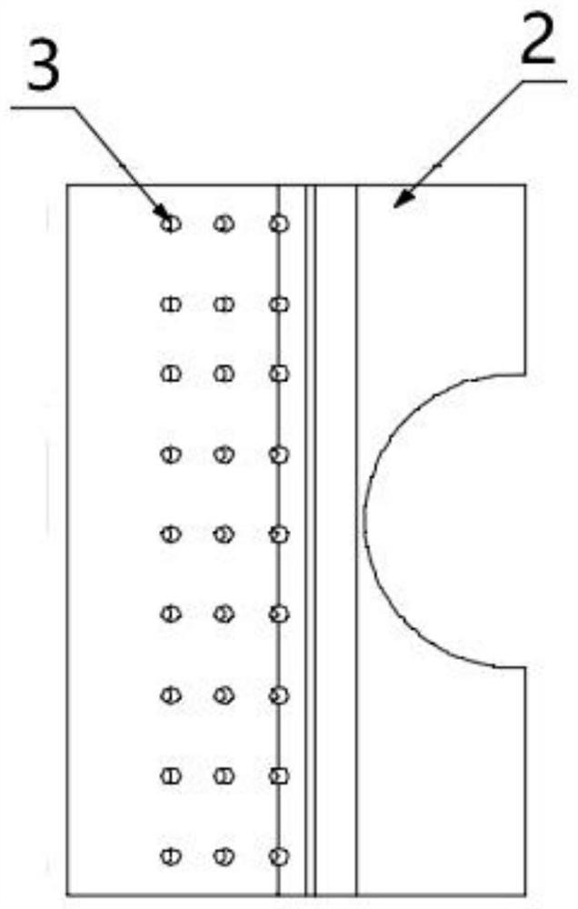
[0025] refer to figure 1 As shown, the preferred embodiment of the present invention provides a kind of tangentially inclined annular film divergent cooling structure, and this cooling structure comprises and comprises flame tube wall 4, gas diaphragm 2 and air intake funnel 5, is opened on the flame tube wall 4 Several air film holes 1 for cooling air to enter the flame tube, several air film sheets 2 for cooling air to flow tangentially alo...


PUM


Abstract

The invention discloses a tangential inclined ring film divergent cooling structure which comprises a flame tube wall surface, a plurality of air film sheets and a plurality of air inlet hoppers, the flame tube wall surface is provided with a plurality of air film holes allowing cooling air to enter a flame tube, and the inner side of the flame tube wall surface is provided with the plurality of air film sheets allowing the cooling air to flow along the flame tube wall surface in the tangential direction. A plurality of air inlet hoppers are arranged on the wall face of the flame tube and located on one side of the air film sheets. The invention belongs to the technical field of combustion chamber cooling, the air film sheets are arranged on the wall face of the flame tube, cooling air films are arranged in the tangential direction of the flame tube, the tangential annular air films are connected end to end to cover the whole wall face of the flame tube, and particularly when a large hole is of a bucket structure, the problem that the wall face is difficult to cool can be well solved. A powerful cooling air film is formed at the downstream of large holes (main combustion holes and mixing holes), so that the reasonability of the wall surface temperature is ensured. The cooling air films move in the tangential direction of the flame tube, and the cooling covering time is prolonged.

Description

technical field [0001] The invention belongs to the technical field of combustion chamber cooling, and relates to a tangentially inclined annular film divergent cooling structure. Background technique [0002] Axial film cooling (following the airflow direction) is a commonly used cooling form of the flame tube. The cooling gas is sprayed out through a certain number of small holes or annular gaps, forming a layer of protective gas along the axial direction between the inner wall of the flame tube and the gas. membrane. Air film cooling is suitable for working environments with various pressure drops and cooling of different parts of the flame cylinder. The air intake methods include total pressure intake, static pressure intake, total static pressure mixed intake and between total pressure intake and static pressure. There are 4 forms of air intake between intakes. Air film cooling can be used alone for flame tube cooling, or it can be combined with convective cooling, im...

Claims


Application Information

Patent Timeline
Patent Type & Authority Applications(China)
IPC IPC(8): F23R3/42
CPCF23R3/42Y02T10/12
Inventor 陈敏敏成胜军杨敏胡建朱明军
Owner AECC HUNAN AVIATION POWERPLANT RES INST
Why Eureka
Try Eureka