A tangentially inclined annular film divergent cooling structure

A divergent cooling and tilting technology, which is applied in the direction of combustion engine, internal combustion piston engine, indirect carbon dioxide emission reduction, etc., can solve the problems of limited cooling capacity, inability to cool the wall well, wall ablation, etc., to ensure rationality, The effect of extending the cooling coverage time and avoiding ablation

Active Publication Date: 2022-07-08
AECC HUNAN AVIATION POWERPLANT RES INST
View PDF16 Cites 0 Cited by
  • Summary
  • Abstract
  • Description
  • Claims
  • Application Information

AI Technical Summary

Problems solved by technology

[0004] The main disadvantages of the existing technical solutions: 1. The gas jet flow of the main combustion hole cuts off the cooling gas film covering the wall, and the local position downstream of the main combustion hole lacks a cooling gas film; 2. A low-velocity zone is usually formed downstream of the gas jet flow of the main combustion hole , in the low-velocity area, it is generally a high-temperature area, which is likely to cause ablation of the wall surface; 3. If the main combustion hole uses an air intake bucket structure, the wall surface temperature of the bucket is usually high, and the existing cooling method cannot be used well 4. If divergent cooling holes are used downstream of the main combustion holes, the cooling capacity is usually limited, and the ablation problem cannot be solved well; in order to solve the above defects, a solution is now provided

Method used


Image

  • A tangentially inclined annular film divergent cooling structure
  • A tangentially inclined annular film divergent cooling structure
  • A tangentially inclined annular film divergent cooling structure

Examples


Embodiment Construction

[0024] The technical solutions in the embodiments of the present invention will be clearly and completely described below with reference to the accompanying drawings in the embodiments of the present invention. Obviously, the described embodiments are only a part of the embodiments of the present invention, rather than all the embodiments. Based on the embodiments of the present invention, all other embodiments obtained by those of ordinary skill in the art without creative efforts shall fall within the protection scope of the present invention.

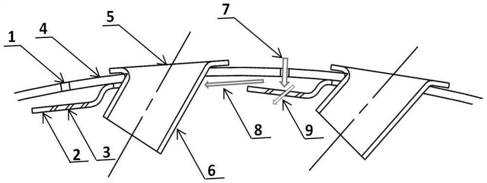
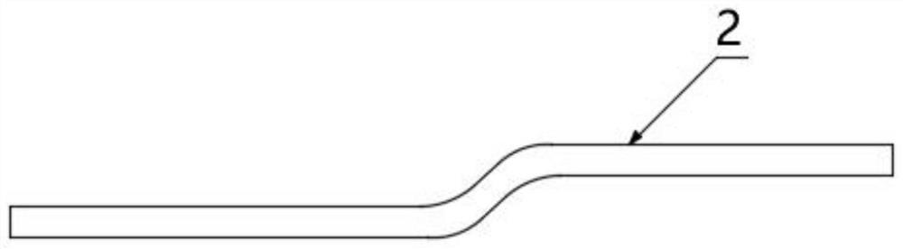
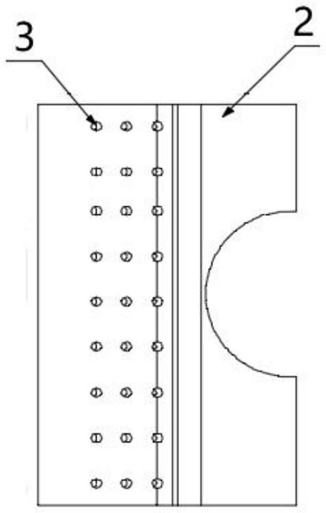
[0025] refer to figure 1 As shown, the preferred embodiment of the present invention provides a tangentially inclined annular film divergent cooling structure, the cooling structure includes a flame tube wall surface 4, a gas diaphragm 2 and an air intake hopper 5, and the flame tube wall surface 4 is provided with A plurality of air film holes 1 that allow cooling air to enter the flame tube, a plurality of air diaphragms 2 for coo...


PUM


Abstract

The invention discloses a tangentially inclined annular film divergent cooling structure, which comprises a flame tube wall surface, a gas membrane sheet and an air intake hopper. The wall surface of the flame tube is provided with a number of gas film holes for allowing cooling air to enter the flame tube. Several gas diaphragms are arranged on the inner side of the cylinder wall to make the cooling air flow tangentially along the wall of the flame cylinder, and several air inlet hoppers are arranged on the wall surface of the flame cylinder, and the air inlet hoppers are located on one side of the gas diaphragm. The invention belongs to the technical field of combustion chamber cooling. A gas film is arranged on the wall surface of the flame tube, and the cooling gas film is arranged in the tangential direction of the flame tube. When the hole is a bucket structure, the problem that the wall surface is difficult to cool can be well solved; a strong cooling gas film is formed downstream of the large hole (main combustion hole, mixing hole) to ensure the rationality of the wall temperature; the cooling gas film along the The flame barrel moves tangentially, extending its cooling coverage time.

Description

technical field [0001] The invention belongs to the technical field of combustion chamber cooling, and relates to a tangentially inclined annular film divergent cooling structure. Background technique [0002] Axial film cooling (in the direction of air flow) is a commonly used cooling form for flame cylinders. The cooling gas is sprayed against the wall through a certain number of small holes or annular gaps, and a layer of axial protective gas is formed between the inner wall of the flame cylinder and the gas. membrane. Air film cooling is suitable for various pressure drop working environments and cooling of different parts of the flame tube. There are 4 forms such as intake air between intake air. Film cooling can be used alone for flame tube cooling, or combined with convection cooling, impingement cooling, etc. to form composite cooling. Pure gas film cooling is most widely used in combustion chambers of current and research engines, as well as advanced engine combu...

Claims


Application Information

Patent Timeline
Patent Type & Authority Patents(China)
IPC IPC(8): F23R3/42
CPCF23R3/42Y02T10/12
Inventor 陈敏敏成胜军杨敏胡建朱明军
Owner AECC HUNAN AVIATION POWERPLANT RES INST
Why Eureka
Try Eureka