Eureka AIR delivers breakthrough ideas for toughest innovation challenges, trusted by R&D personnel around the world.

A low heat dissipation composite structure piston

A combination structure, low heat dissipation technology, applied in the direction of pistons, machines/engines, mechanical equipment, etc., can solve the problem of easy cracking and falling off of heat insulation coating, limited heat insulation capacity of metal heat insulation pad, and difficult to solve reliability problems, etc. problem, to achieve the effect of light weight, avoiding ablation problem, and simple processing

Active Publication Date: 2021-05-28
CHINA NORTH ENGINE INST TIANJIN
View PDF0 Cites 0 Cited by
  • Summary
  • Abstract
  • Description
  • Claims
  • Application Information

AI Technical Summary

Problems solved by technology

[0005] The second is to adopt a steel top aluminum skirt heat insulation structure, which adds a metal heat insulation pad between the piston top and the aluminum body. The piston top is made of heat-resistant steel, and the heat transfer from the piston top to the aluminum body is reduced through the metal heat insulation pad. , so as to reduce the temperature of the aluminum body and save the cooling oil passage structure. Although the piston top of this type of structure can withstand higher temperatures, the heat insulation capacity of the metal heat insulation pad is limited and the overall mass is relatively large;
[0006] The third is to spray a heat-insulating coating on the top surface of the overall aluminum piston to reduce the heat transfer from the combustion chamber to the piston and reduce the surface temperature of the piston. However, the heat-insulating coating is easily affected by the thermal deformation of the piston. Problems such as cracking and falling off occur, and its reliability problem is still difficult to solve

Method used


Image

  • A low heat dissipation composite structure piston
  • A low heat dissipation composite structure piston
  • A low heat dissipation composite structure piston

Examples


Embodiment Construction

[0030] It should be noted that, in the case of no conflict, the embodiments of the present invention and the features in the embodiments can be combined with each other.

[0031] In describing the present invention, it should be understood that the terms "center", "longitudinal", "transverse", "upper", "lower", "front", "rear", "left", "right", " The orientations or positional relationships indicated by "vertical", "horizontal", "top", "bottom", "inner" and "outer" are based on the orientations or positional relationships shown in the drawings, and are only for the convenience of describing the present invention and Simplified descriptions, rather than indicating or implying that the device or element referred to must have a particular orientation, be constructed and operate in a particular orientation, and thus should not be construed as limiting the invention. In addition, the terms "first", "second", etc. are used for descriptive purposes only, and should not be understood ...


PUM


Abstract

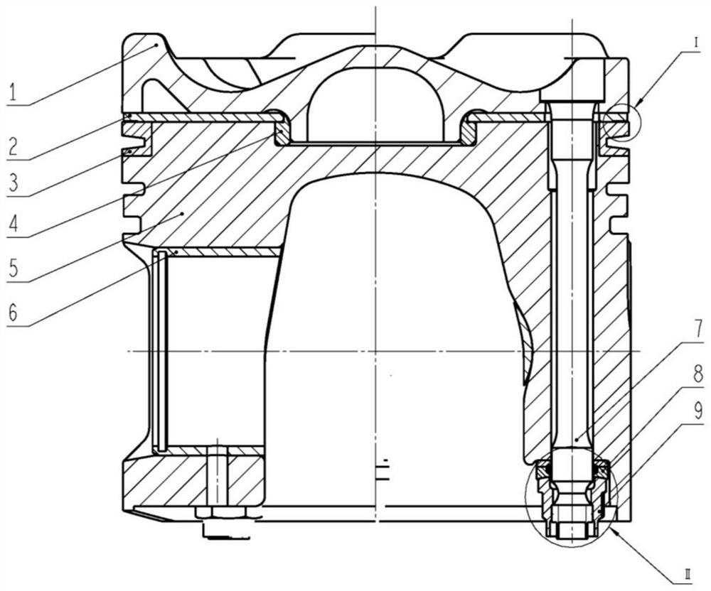
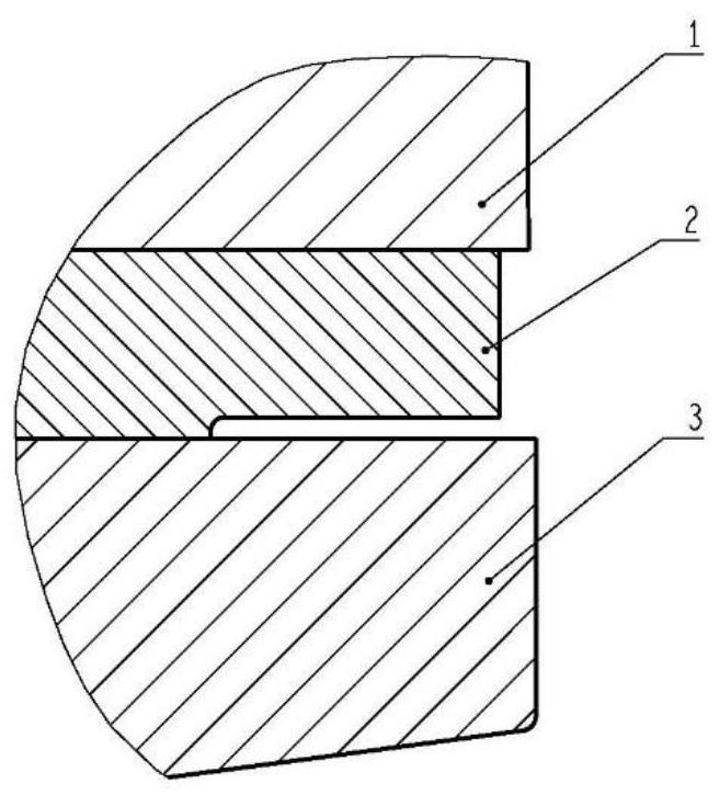
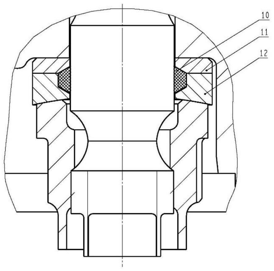
The invention provides a piston with a low heat dissipation combined structure, which includes a piston steel top, a heat insulation pad, an independent ring seat, a positioning ring, an aluminum body, a bush, a bolt, a gasket set and a lock nut; the piston steel top, The heat insulation pad and the aluminum body are connected in turn by bolts; the first ring seat of the piston adopts an independent ring seat structure, which is installed on the top of the aluminum body and pressed by the piston steel top and the heat insulation pad; the concave structure in the middle of the piston steel top An air-tight heat-insulation cavity is formed between the aluminum body and the outer extension of the concave structure of the steel top of the piston. The invention effectively isolates the heat transfer from the top of the piston to the aluminum body, and performs heat insulation in three forms: air heat insulation, low heat dissipation metal pad physical heat insulation and combined structure contact thermal resistance, so that the temperature of the aluminum body is controlled within a reasonable range, and its mechanical properties are improved. No substantial degradation occurs.

Description

technical field [0001] The invention belongs to the technical field of engine pistons, in particular to a piston with a low heat dissipation combined structure. Background technique [0002] At present, four-stroke diesel engines mostly use cast aluminum pistons to reduce the mass of the pistons and reduce the reciprocating inertial force of the pistons. However, the limit temperature that the cast aluminum pistons can withstand is low, about 420 degrees. As the combustion pressure of the engine continues to increase , the temperature of the piston continues to rise, and the cast aluminum piston can no longer withstand such a high temperature, which can easily lead to piston ablation. [0003] In order to solve the above problems, there are generally three ways: [0004] One is the combined piston with steel top and aluminum skirt, and a cooling oil passage is set between the piston top and the aluminum body. During the working process, the temperature of the piston top and...

Claims


Application Information

Patent Timeline
Patent Type & Authority Patents(China)
IPC IPC(8): F02F3/00F02F3/12F02F3/28
CPCF02F3/0023F02F3/0084F02F3/0092F02F3/12F02F3/28
Inventor 王延荣张利敏许春光刘玉婷张晓静
Owner CHINA NORTH ENGINE INST TIANJIN
Why Eureka
Eureka Blog
Learn More