Electrical etching machine of metal cutter template

An electrolytic etching and metal knife technology, applied in the direction of electrolytic process, electrolytic components, metal processing equipment, etc., can solve the problems of accurate positioning, roughness, and increased production cost of difficult-to-etch metal products

Active Publication Date: 2014-07-09
常州正成机电科技有限公司
View PDF9 Cites 0 Cited by
  • Summary
  • Abstract
  • Description
  • Claims
  • Application Information

AI Technical Summary

Problems solved by technology

The device and the method of use have the following disadvantages: since the metal product to be etched is in contact with the negative electrode and the positive electrode, it is difficult to ensure that the upper and lower surfaces of the metal product to be etched are very smooth, therefore, it is easy to produce the metal product to be etched and the positive electrode The poor contact of the metal product to be etched can easily lead to ablation and scrapping of the metal product to be etched; the back of the metal product to be etched needs to be protected against electrolysis, otherwise the back will also be consumed, which increases production costs and affects processing efficiency; due to the electrolyte The liquid storage block passes through the small holes evenly distributed on the movable contact electrode, and flows to the surface of the metal product to be etched. Therefore, the etching is relatively fast on the metal product to be etched corresponding to the small holes, and the etching in other places is relatively fast. Slow, it is very easy to make the surface of the metal product to be etched uneven, uneven, and not smooth, and it cannot meet the requirements of large etching depth, high uniformity, and high precision at all. Accurate positioning of etched metal products on the electrode, it is not convenient to install the workpiece and observe the etching situation during the electrolytic etching process

Method used


Image

  • Electrical etching machine of metal cutter template
  • Electrical etching machine of metal cutter template
  • Electrical etching machine of metal cutter template

Examples


Embodiment Construction

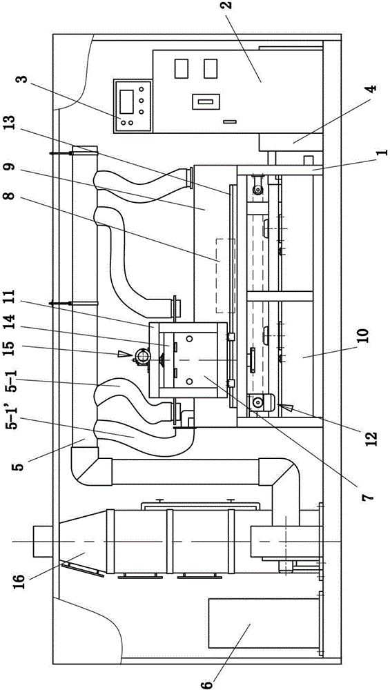
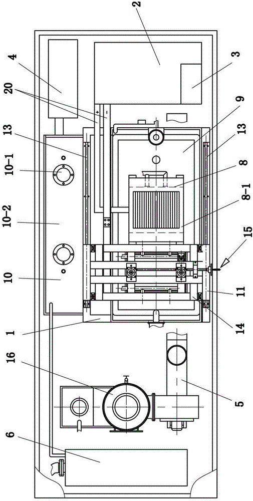
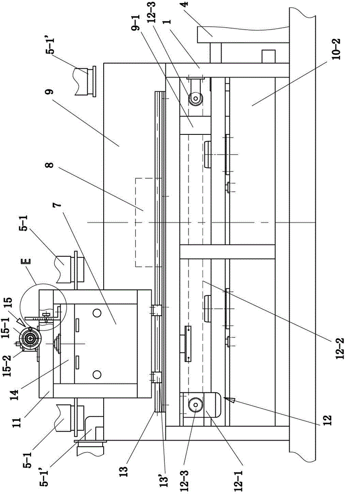
[0049] like Figure 1~12 , 22, 23, and 24, a metal knife template electrolytic etching machine includes a frame 1, an upper electrode 7, a lower electrode 8 and an electrolyte collection tank 9, wherein the electrolyte collection tank 9 is located on the frame 1 , the lower electrode 8 is located in the electrolyte collection tank 9, the frame 1 is also moved with a translation frame 11, the upper electrode 7 is mounted on the translation frame 11, and the translation frame 11 is located on the upper There are at least two liquid outlets 7-1 next to the electrode 7, and the liquid outlets of the liquid outlets 7-1 are all facing the bottom of the upper electrode 7 and the space below the bottom surface. When the translation frame 11 moves, the upper electrode 7 and the outlet The liquid container 7-1 can pass above the lower electrode 8, the upper surface of the lower electrode 8 is provided with an insulating workpiece support 8-1, and the workpiece support 8-1 has a liquid c...


PUM


Abstract

The invention discloses an electrical etching machine of a metal cutter template, which comprises a machine frame, an upper electrode, a lower electrode and an electrolyte collecting tank. A translation frame is further matched on the machine frame in moving mode, the upper electrode is installed and connected onto the translation frame, at least two liquid outlet devices communicated with a liquid supplying device are arranged on the translation frame and beside the upper electrode, a liquid outlet of each liquid outlet device faces toward the bottom of the upper electrode and toward a space under the bottom face of the upper electrode, an insulating workpiece support piece is arranged on the upper surface of the lower electrode and provided with a liquid passageway, or a plurality of insulating workpiece support strips are arranged on the upper surface of the lower electrode, the gaps between adjacent workpiece support strips form the liquid passageway, a liquid flow passage communicated with the upper surface of the lower electrode is arranged inside the lower electrode or on the lateral face of the lower electrode, and the liquid flow passage is communicated with the liquid passageway. The electrical etching machine generates no erosion and can meet the metal cutter template etching requirements for large etching depth, high evenness and high accuracy.

Description

technical field [0001] The invention relates to a device for performing electrolytic etching on a metal knife template. Background technique [0002] The document with the Chinese patent document number CN2220372 discloses a metal graphic engraving machine. The device includes an electrode (negative electricity) on the upper part of the chassis, a moving contact and its lifting mechanism and a liquid supply mechanism. The output end of the liquid supply mechanism is located at the movable contact. Above or below the electrode (positive electricity), the working process is as follows: first, place the metal product to be etched on the electrode on the upper part of the chassis, and maintain good electrical contact; make the moving contact electrode and the electrode on the upper part of the chassis respectively bring Positive electricity and negative electricity, start the switch of the liquid suction pump, so that the electrolyte in the liquid storage tank is transported to ...

Claims


Application Information

Patent Timeline
Patent Type & Authority Patents(China)
IPC IPC(8): C25F7/00B23H3/00
Inventor 周丁政
Owner 常州正成机电科技有限公司
Why Eureka
Try Eureka