Helicopter rotor shaft bearing set testing machine

A technology of testing machine and bearing group, which is applied in the direction of mechanical bearing testing, etc., can solve the problems of inaccurate test results, impossibility of testing due to the influence of the use of rotor shaft bearings, reduction of grease, etc., and achieve the comprehensive effect of the testing method

Active Publication Date: 2022-06-17
C&U CO LTD +3
View PDF6 Cites 0 Cited by
  • Summary
  • Abstract
  • Description
  • Claims
  • Application Information

AI Technical Summary

Problems solved by technology

However, in the actual operation process, it is not possible to test the influence of different greases on the rotor shaft bearings. Even if the bearings packaged with different types of grease are used for testing each time, it is easy to reduce the grease during the test process and cause the test Inaccurate results occur

Method used


Image

  • Helicopter rotor shaft bearing set testing machine
  • Helicopter rotor shaft bearing set testing machine
  • Helicopter rotor shaft bearing set testing machine

Examples


Embodiment 1

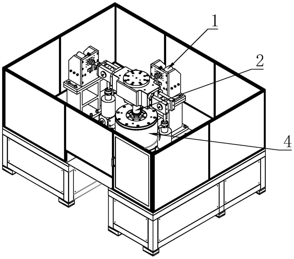
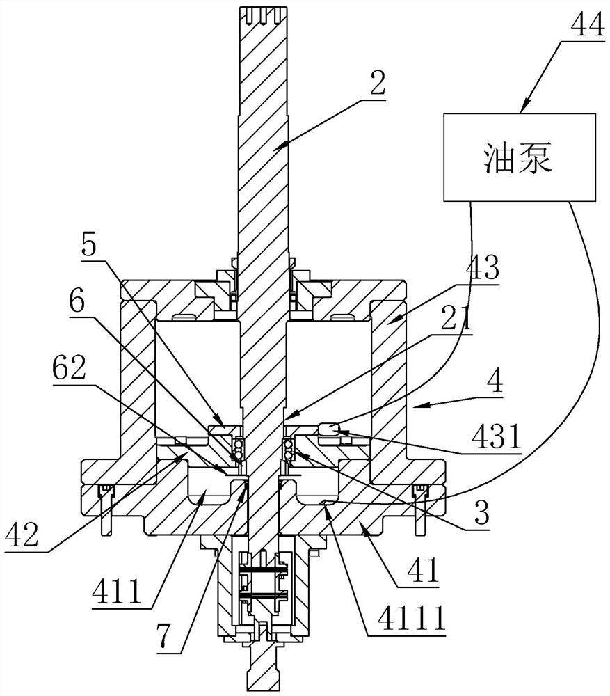
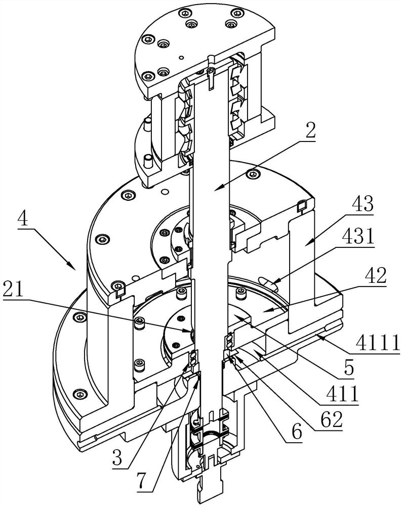
[0025] Helicopter rotor shaft bearing set test machine, including loading part 1, test mandrel 2, test bearing 3 sleeved on test mandrel 2, assembly assembly 4 for installing test mandrel 2 and test bearing 3, assembly assembly 4 It includes a fixed base 41 for rotatably connecting the test mandrel 2, a bushing 42 for assembling the test bearing 3, and a cover 43 assembled with the fixed base 41. The bushing 42 is located inside the cover 43 and the outer edge of the bushing 42 is Abut against the inner wall of the cover body 43; the fixed base 41 has an oil storage groove 411 for receiving the lubricating grease dropped by the test bearing 3, and the oil storage groove 411 is provided with an oil outlet 4111 communicating with the outside; the inner ring of the test bearing 3 is connected to the test bearing 3 The mandrel 2 is fixedly matched, and the outer ring is fixedly matched with the bushing 42; the cover body 43 is provided with an oil inlet hole 431. When grease is inj...

Embodiment 2

[0033] Based on the solution of Example 1, another optimization is made: a protrusion 51 is provided on the side of the pressure plate 5 opposite to the outer ring of the test bearing 3. When the pressure plate 5 and the bushing 42 are assembled and fixed to the outer ring of the test bearing 3, the protrusion 51 is pressed against the outer ring of the test bearing 3. The outer ring of the test bearing 3; when the protrusion 51 abuts the outer ring of the test bearing 3, the pressure plate 5 and the side surface of the test bearing 3 have a gap for the grease to flow through.

[0034] On the one hand, the design of the protrusion 51 can fix the outer ring of the test bearing 3 in a targeted manner, and on the other hand, there is a gap between the pressure plate 5 and the bearing, and the gap 21 on the test mandrel 2 can be used to fit the gap 21. An oil channel can be formed, so that the grease can flow into the test bearing 3 more conveniently.

[0035] In order to further ...

Embodiment 3

[0039] Further optimization is made for the oil baffle 62 of the second embodiment: the radial length of the oil baffle 62 extends to the position of the oil storage groove 411 . The radial extent of the oil baffle 62 can directly reach the position of the oil storage tank 411 , which avoids the problem of poor throwing effect at low rotation speed.

[0040] In a further arrangement, a sealing ring 7 is also provided between the test mandrel 2 and the fixed base 41 , and the sealing ring 7 is located within the coverage area of ​​the oil baffle 62 . By using the sealing ring 7, an additional line of defense can be used to ensure the sealing effect.


PUM


Abstract

The invention discloses a testing machine for a helicopter rotor shaft bearing group, comprising a loading part, a test mandrel, a test bearing sleeved on the test mandrel, an assembly assembly for installing the test mandrel and the test bearing, the assembly assembly includes a The fixed base connected to the test mandrel, the bush used to assemble the test bearing, and the cover assembled with the fixed base, the bush is located inside the cover and the outer edge of the bush is against the inner wall of the cover; the fixed base has a The oil storage tank for the grease dropped by the bearing, the oil storage tank is provided with an oil outlet hole connected to the outside; the inner ring of the test bearing is fixedly matched with the test mandrel, and the outer ring is fixedly matched with the bushing; the cover is provided with an oil inlet hole , when the grease is injected into the oil inlet, the grease spreads into the test bearing; the oil inlet and the oil outlet are connected by an oil pump. The invention can conveniently supply different kinds of lubricating grease and maintain the supply of lubricating grease to the bearing all the time.

Description

technical field [0001] The invention relates to a bearing detection device, in particular to a bearing group testing machine capable of simulating the working condition of a helicopter rotor shaft. Background technique [0002] During the flight of the helicopter, the failure of any component can have catastrophic consequences. Therefore, it is a very serious and important work to determine the service life of helicopter components. In order to accurately determine the service life of the components of the helicopter, the usual practice is to carry out the fatigue test of the components of the helicopter under simulated real working conditions, and then divide the fatigue life obtained by the test by a safety factor, which is the component of the aircraft. service life. [0003] In order to overcome the above problems, the Chinese patent application number CN201810889457.0 discloses a hydraulic loading system for a combined bearing testing machine supporting the main rotor...

Claims


Application Information

Patent Timeline
Patent Type & Authority Patents(China)
IPC IPC(8): G01M13/04
CPCG01M13/04
Inventor 黄聚钱韦治国谷广存
Owner C&U CO LTD
Why Eureka
Try Eureka