Pipe clamp

A technology of clamps and closing elements, which is applied in the directions of pipe supports, pipe/pipe joints/pipes, sleeve/socket connections, etc., can solve the problems of non-existence, reduce the risk of failure, high load capacity, reduce The effect of clamping force

Pending Publication Date: 2021-07-27
FISCHERWERKE ARTUR FISCHER GMBH & CO KG
View PDF1 Cites 0 Cited by
  • Summary
  • Abstract
  • Description
  • Claims
  • Application Information

AI Technical Summary

Problems solved by technology

[0003] A disadvantage of the known pipe collar is that the tensioning screw acts on the outwardly angled flange and the outwardly angled portion of the closing element outside of an imaginary ring which does not have an outwardly angled The flange and the two clip bows without the outwardly angled part of the closing element form

Method used


Image

  • Pipe clamp
  • Pipe clamp
  • Pipe clamp

Examples


Embodiment Construction

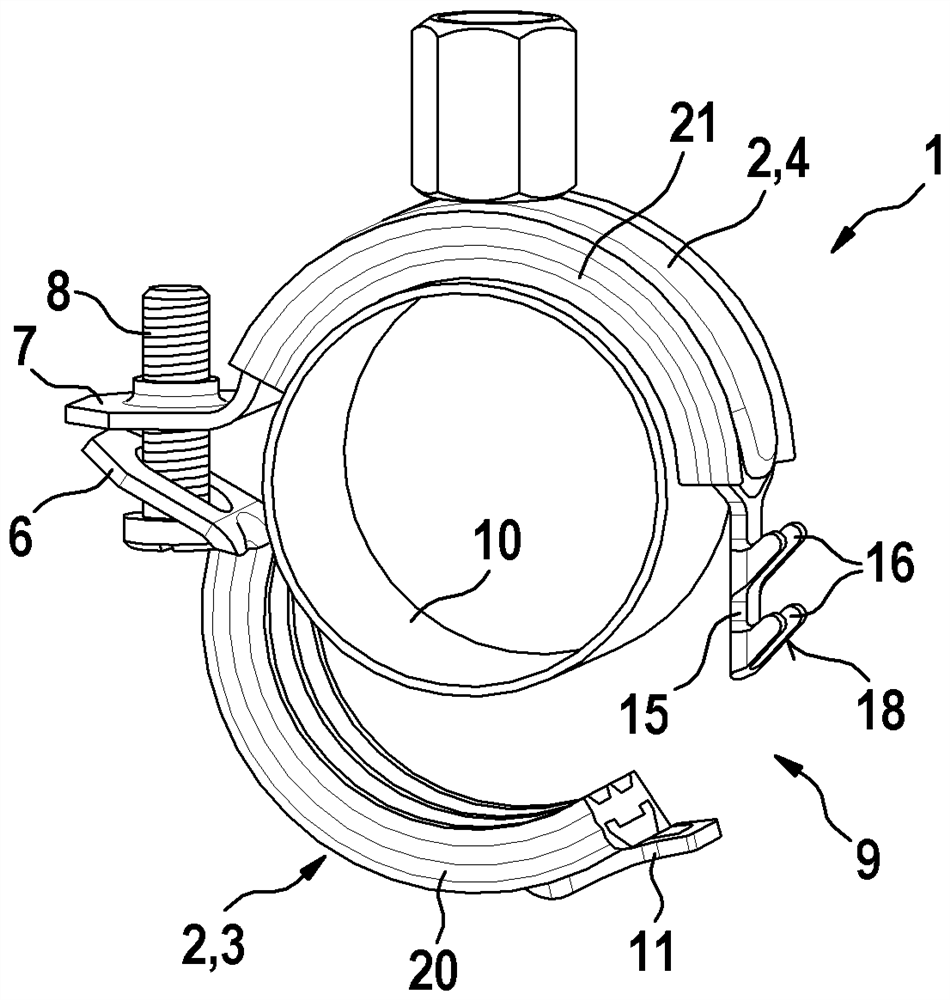
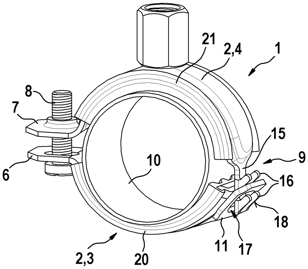
[0023] The pipe clamp 1 according to the invention shown in the drawing has a clamp body 2 with two circular arc-shaped clamp bows 3 , 4 which are bent from strips, but can also composed of other materials.

[0024] The second clamp bow 4 of the two clamp bows has a fastening nut 5 welded on the outside or otherwise arranged for fastening the pipe clamp 1 to a wall or ceiling, for example. The pipe clamp 1 can have no clamping nut 5 but, for example, a screw (not shown) protruding from one of the two clamp bows 3 , 4 .

[0025] At a second circumferential position, the two clamp bows 3 , 4 have flanges 6 , 7 protruding radially or precisely parallel to the axial plane, the first of which 6 has a through hole through which a tensioning screw 8 passes, and the second one of the flanges 7 has an internally threaded hole into which the tensioning screw 8 is screwed. The two clamp bows 3, 4 are thus hingedly connected, and as figure 2 shown, can be pivoted separately from each ot...


PUM


Abstract

In order to prevent a pipe clamp (1) from bending when subjected to a load in the sense of opening, the invention provides a closing element (11) extending in the circumferential direction, which hangs by itself when the pipe clamp (1) is closed and which acts on the circumference of the clamp body (2) so that only tensile force in the circumferential direction acts and no bending moments act.

Description

technical field [0001] The invention relates to a pipe clamp having the features of the preamble of claim 1 . Background technique [0002] Laid-open document DE 36 01 815 A1 discloses a pipe collar. The known pipe clamp has two semicircular clamp bows bent from laths, which can be connected or have been connected to form a circle at opposite circumferential positions by means of tensioning screws. Shaped clamp body. At one of the two peripheral positions, the pipe collar has a closing element bent from a lath hingedly suspended from a through hole near the end of one of the two collar bows , thereby enabling the closing element to pivot outwards. The closing element is angled radially outward and has a T-shaped window through which the screw head of the tensioning screw can penetrate and hook back into the bent end of the closing element. The tensioning screw is screwed into a threaded hole in the radially outwardly angled flange at the associated end of the further cla...

Claims


Application Information

Patent Timeline
Patent Type & Authority Applications(China)
IPC IPC(8): F16L21/06
CPCF16L21/065F16L3/1025F16L3/1083
Inventor B·格迈纳T·科桑克
Owner FISCHERWERKE ARTUR FISCHER GMBH & CO KG
Why Eureka
Try Eureka