
Turbine box for butterfly valve driving device

A driving device, turbine box technology, applied in the direction of valve device, valve operation/release device, valve details, etc., can solve the problems of poor adaptability, worm wear, insufficient safety, etc.

Pending Publication Date: 2021-07-30
瑞达自控阀门股份有限公司
View PDF5 Cites 0 Cited by
  • Summary
  • Abstract
  • Description
  • Claims
  • Application Information

AI Technical Summary

Problems solved by technology

[0003] However, in the existing drive gearbox structure, most of the worm gears are simply positioned and installed. This requires accurate alignment installation, which is not conducive to adjusting the installation gap and causes serious wear of the worm. In this way, when an emergency shutdown is required, the worm gear cannot be separated and driven directly through the backup structure, which has poor adaptability and insufficient safety, and needs to be improved.

Method used


Image

  • Turbine box for butterfly valve driving device
  • Turbine box for butterfly valve driving device
  • Turbine box for butterfly valve driving device

Examples


Embodiment Construction

[0032] The following will clearly and completely describe the technical solutions in the embodiments of the present invention in conjunction with the accompanying drawings in the embodiments of the present invention; obviously, the described embodiments are only part of the embodiments of the present invention, not all embodiments, based on The embodiments of the present invention and all other embodiments obtained by persons of ordinary skill in the art without making creative efforts belong to the protection scope of the present invention.

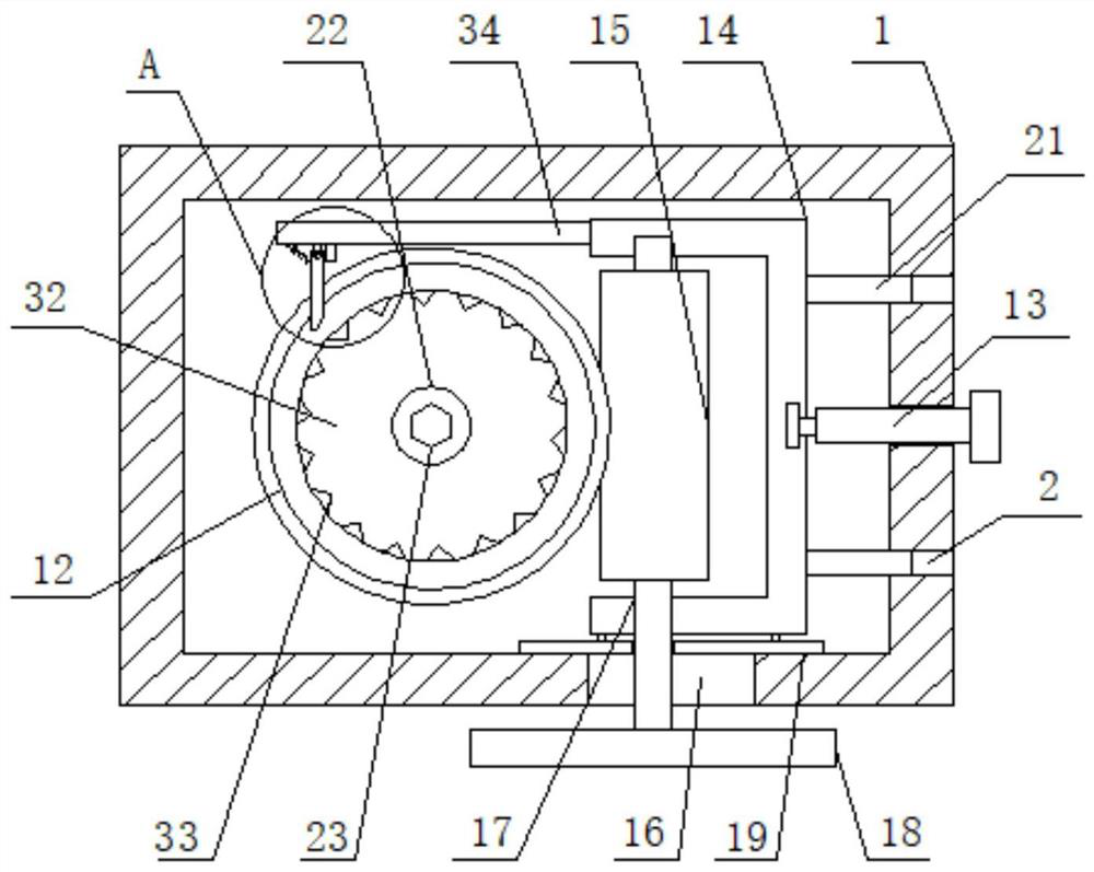
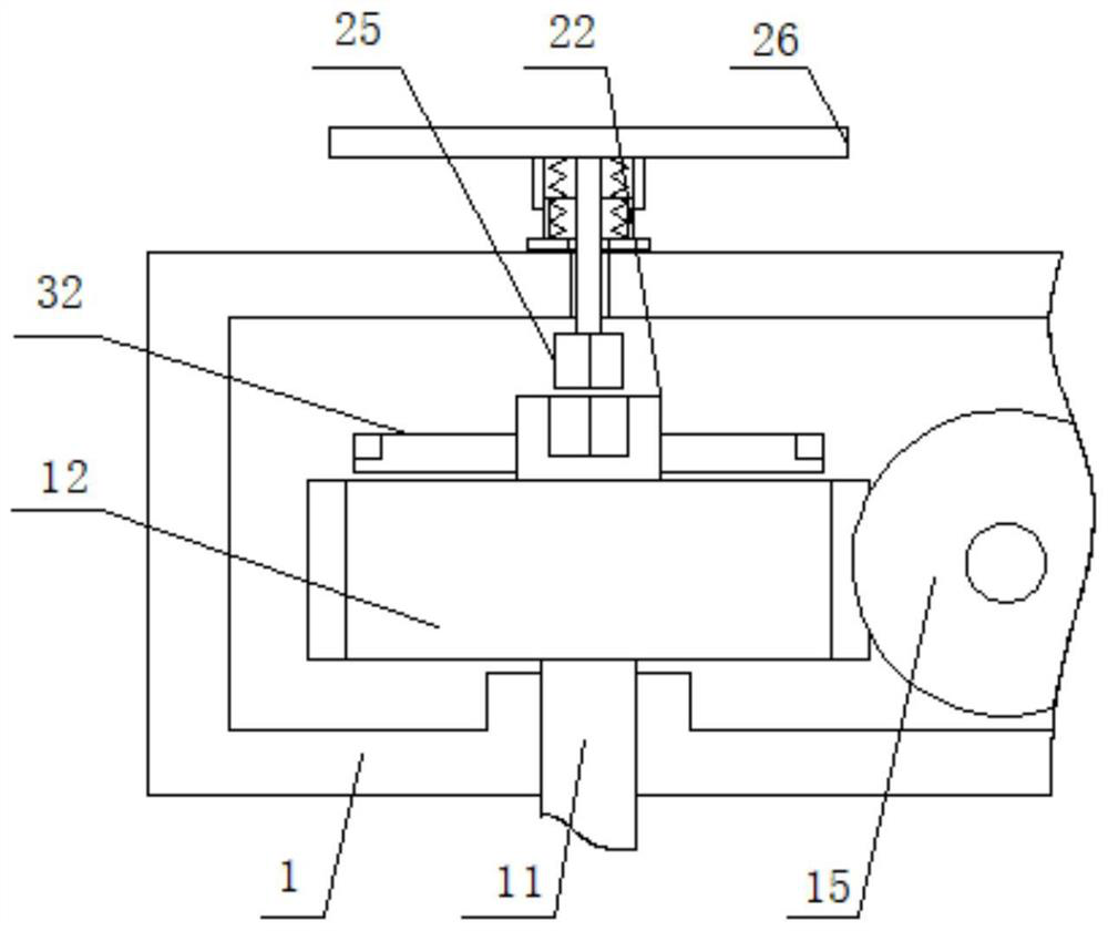
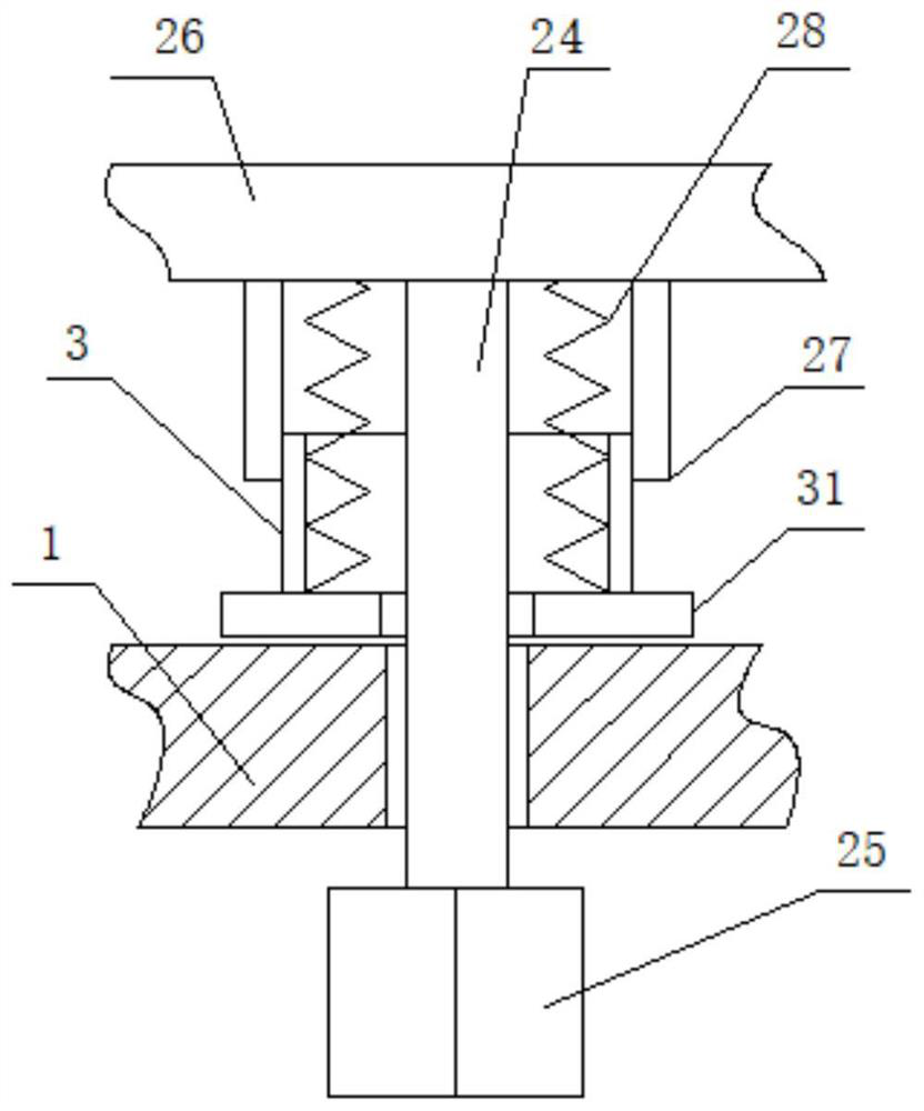
[0033] see Figure 1-4 , a turbine box for a butterfly valve driving device, including a box body 1, please refer to figure 1 and figure 2 One side surface of the box body 1 is rotatably connected with an installation shaft 11, one end surface of the installation shaft 11 is rotatably installed with a worm wheel 12, and the other side surface of the box body 1 is threadedly connected with an adjusting threaded rod 13, and one end of th...


PUM


Abstract

The invention discloses a turbine box for a butterfly valve driving device. The turbine box comprises a box body, wherein a mounting shaft is rotationally connected to the surface of one side of the box body, a worm gear is rotationally mounted on the surface of one end of the mounting shaft, an adjusting threaded rod is in threaded connection to the surface of the other side of the box body, and a U-shaped frame is rotationally connected to one end of the adjusting threaded rod; the surface of one side of the U-shaped frame is slidably connected to the side surface of the box body, a worm is rotatably mounted on the surface of the other side of the U-shaped frame, the surface of the worm is meshed with the surface of one side of the worm gear, a long-strip-shaped through groove is formed in the side surface of one end of the box body, and an adjusting shaft is connected to one end of the worm; and the surface of one end of the adjusting shaft is slidably connected to the side surface of the long-strip-shaped through groove, an adjusting hand wheel is fixedly connected to the other end of the adjusting shaft, and a protection plate is fixedly connected to the side surface of the other end of the U-shaped frame, so that use convenience and stability can be greatly improved, and safety and high efficiency of driving adjustment are guaranteed.

Description

technical field [0001] The invention relates to the field of butterfly valves, in particular to a turbine box for a butterfly valve driving device. Background technique [0002] In the current industrial production, the use of butterfly valves is very common. In the drive control of butterfly valves, the turbine box is usually connected to the shaft end to control the adjustment, and the internal worm gear is used for transmission and locking. [0003] However, in the existing structure of the drive turbine box, most of the worm gears are simply positioned and installed. This requires accurate alignment installation, which is not conducive to adjusting the installation gap and causes serious wear of the worm gear. When emergency shutdown is needed like this, the worm wheel cannot be separated and driven directly by the backup structure, which has poor adaptability and insufficient safety, and needs to be improved. Contents of the invention [0004] Aiming at the problems ...

Claims


Application Information

Patent Timeline
IPC IPC(8): F16K31/60F16K31/53F16K31/44
CPCF16K31/60F16K31/53F16K31/44
Inventor 金松景
Owner 瑞达自控阀门股份有限公司
Learn More