Small table plate device

A small table board and table board technology, which is applied to tables, extendable tables, household appliances, etc., can solve the problems of small table board area, restricting the load capacity of the table board, and the length of the stretching slide rail cannot be too long, etc. Achieve the effect of meeting the stretching distance, ensuring the strength and stability of the table board

Active Publication Date: 2012-07-04
YANFENG ADIENT SEATING CO LTD
View PDF6 Cites 7 Cited by
  • Summary
  • Abstract
  • Description
  • Claims
  • Application Information

AI Technical Summary

Problems solved by technology

However, these small table boards have a small area and can only place some small items, and cannot place large items such as computers.
see figure 1 , the existing small table board 2 applied to the seat back 1 generally has a small area, and because the stretched slide rail 3 is composed of two slide rails, and the length of the stretched slide rail 3 cannot be too long, so The stretching distance of the small table 2 on the seat back 1 is small, and the distance between the small table 2 and the seat back 1 is relatively short after the small table 2 is pulled out. Once the front passenger needs to lie down and the seat back 1 is put down, the small table The angle between the board 2 and the seat back 1 is small, and the laptop 4 cannot be placed on the small table board 2. Even if it is placed, the screen of the laptop 4 cannot be fully opened, and it is not suitable for rear passengers to use the laptop 4 for office work. and entertainment requirements
Moreover, the locking mechanism and the unlocking mechanism of the small table plate at the back of the existing table and chair backrest are arranged on the backrest, and the locking mechanism and the unlocking mechanism are exposed and unsightly.
In addition, the slide rail in the small table on the back of the existing seat is directly connected to the seat back, so that the load-bearing capacity of the table is restricted

Method used


Image

  • Small table plate device
  • Small table plate device
  • Small table plate device

Examples


Embodiment Construction

[0054] In order to make the technical means, creative features, goals and effects achieved by the present invention easy to understand, the implementation of the present invention will be further described below in conjunction with specific illustrations.

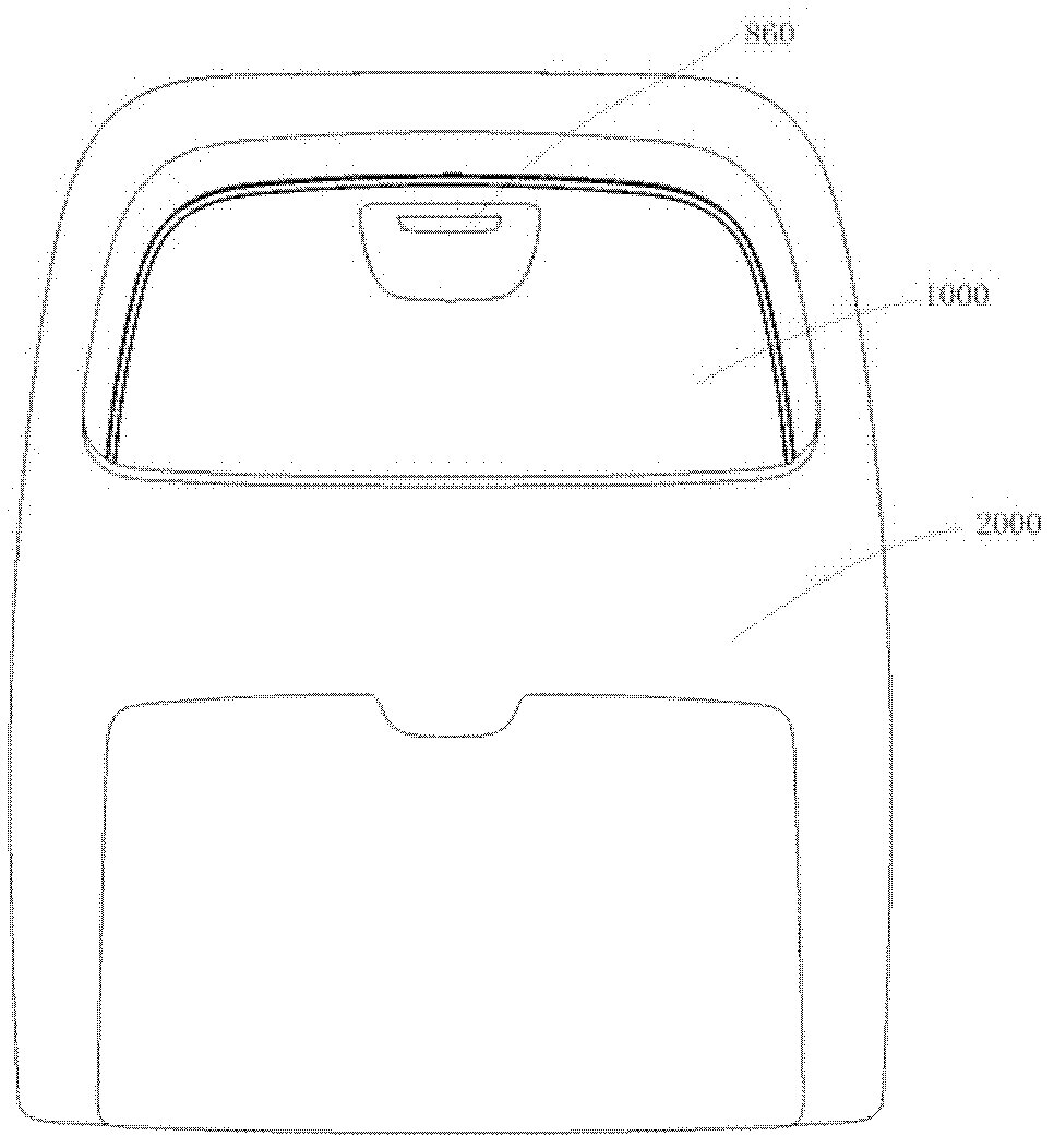
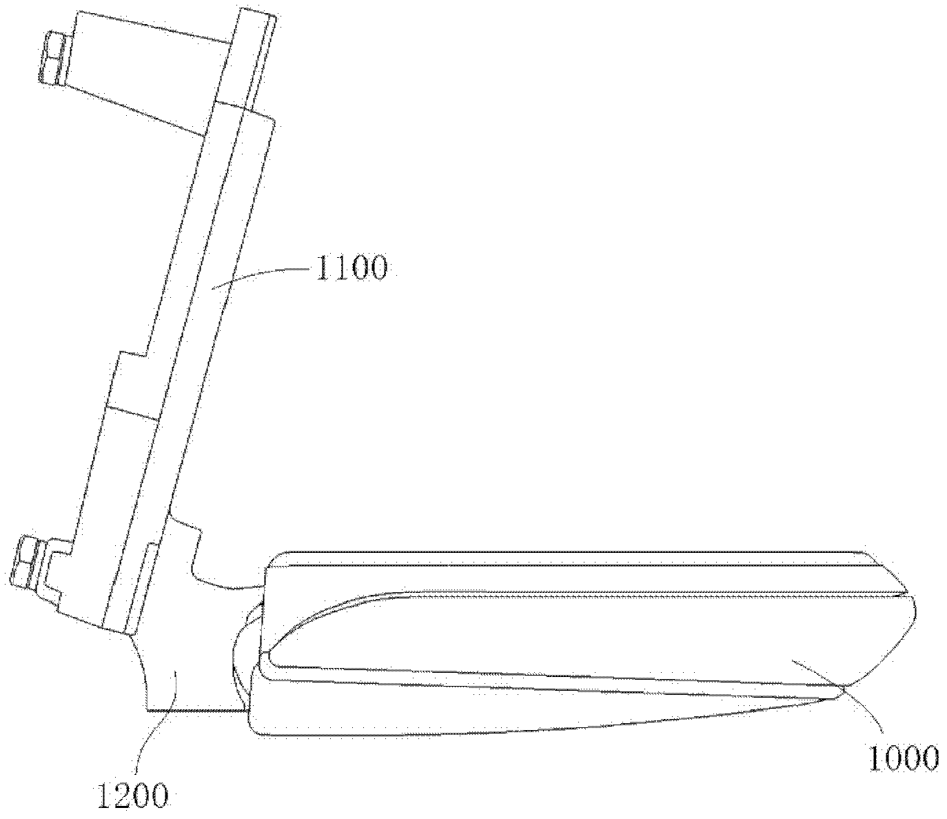
[0055] see figure 2 , the tray assembly 1000 in the tray device of the present invention is installed in the seat back 2000, the button switch 860 can be held by hand to unlock the tray assembly 1000 and the fixing part 1100 Turn the small table assembly assembly 1000 in the small table assembly device of the present invention into a horizontal shape around the hinge part 1200, and then place objects on the desktop of the small table assembly assembly 1000 (see image 3 ). Of course it can also be Figure 4 In that way, the tray assembly assembly 1000 is pulled to the middle position according to the needs of each person; or as Figure 5 In that way, the tray assembly assembly 1000 is pulled to its final position.

[0...


PUM


Abstract

The invention discloses a small table plate device which comprises a small table plate component assembly. The small table plate component assembly is divided into an inner table plate part assembly and an outer table plate part assembly which are mutually connected, wherein the inner table plate part assembly comprises an inner small table plate part, a slide rail fixing seat arranged on the inner small table plate part, a slide rail assembly arranged on the slide rail fixing seat, and a locking part assembly; the outer table plate part assembly comprises an outer small table plate part and an unlocking part assembly arranged on the outer small table plate part; the unlocking part assembly acts on the locking part assembly to drive to implement unlocking between the locking part assembly and a fixing part; and the slide rail assembly is formed by a main slide rail component, at least one middle slide rail component and a tail end slide rail component which are in slide fit mutually. In a limited space, a small table plate can be pulled out by a longer distance, so that not only is the tension distance of the table plate met, but also the strength and the using stability of the table plate are ensured.

Description

technical field [0001] The invention relates to a small table board device capable of reciprocating rotation and reciprocating stretching with a long stretching distance and capable of placing various articles. Background technique [0002] At present, it is often necessary to set some small table boards that can be folded and stretched in rooms, office spaces, conference halls, fast food restaurants, and vehicle seats. But these small table boards are less in area, and some very small items can only be placed, and larger items such as computers cannot be placed. see figure 1 , the existing small table board 2 applied to the seat back 1 generally has a small area, and because the stretched slide rail 3 is composed of two slide rails, and the length of the stretched slide rail 3 cannot be too long, so The stretching distance of the small table 2 on the seat back 1 is small, and the distance between the small table 2 and the seat back 1 is relatively short after the small ta...

Claims


Application Information

Patent Timeline
Patent Type & Authority Applications(China)
IPC IPC(8): A47B1/05
Inventor 朱敏张韦炜李侠徐东海白玉刚张帅
Owner YANFENG ADIENT SEATING CO LTD
Why Eureka
Try Eureka