Liquid carbon dioxide fire extinguishing device for emergency rescue in disaster areas

A technology for liquid carbon dioxide and emergency rescue, which is applied in fire rescue and other directions, and can solve problems affecting the injection efficiency of liquid carbon dioxide, insufficient adaptability of technical performance to the environment, and lack of pressure compensation for storage tanks, etc., so as to reduce the number of fillings and achieve stable and reliable performance , The effect of reducing maintenance costs

Inactive Publication Date: 2014-12-17
CHINA COAL TECH ENG GRP CHONGQING RES INST
View PDF13 Cites 6 Cited by
  • Summary
  • Abstract
  • Description
  • Claims
  • Application Information

AI Technical Summary

Problems solved by technology

The existing mobile liquid carbon dioxide fire extinguishing device generally includes a storage tank for storing liquid carbon dioxide and a base for carrying and fixing the storage tank. The storage tank is connected with a pressure gauge, a liquid level gauge and a control valve group. Monitor the pressure in the tank in real time, monitor the liquid level in the tank in real time through the liquid level gauge, and realize the functions of filling, draining, and pressure relief through the control valve group and pipeline group; however, the technica

Method used


Image

  • Liquid carbon dioxide fire extinguishing device for emergency rescue in disaster areas
  • Liquid carbon dioxide fire extinguishing device for emergency rescue in disaster areas
  • Liquid carbon dioxide fire extinguishing device for emergency rescue in disaster areas

Examples


Embodiment Construction

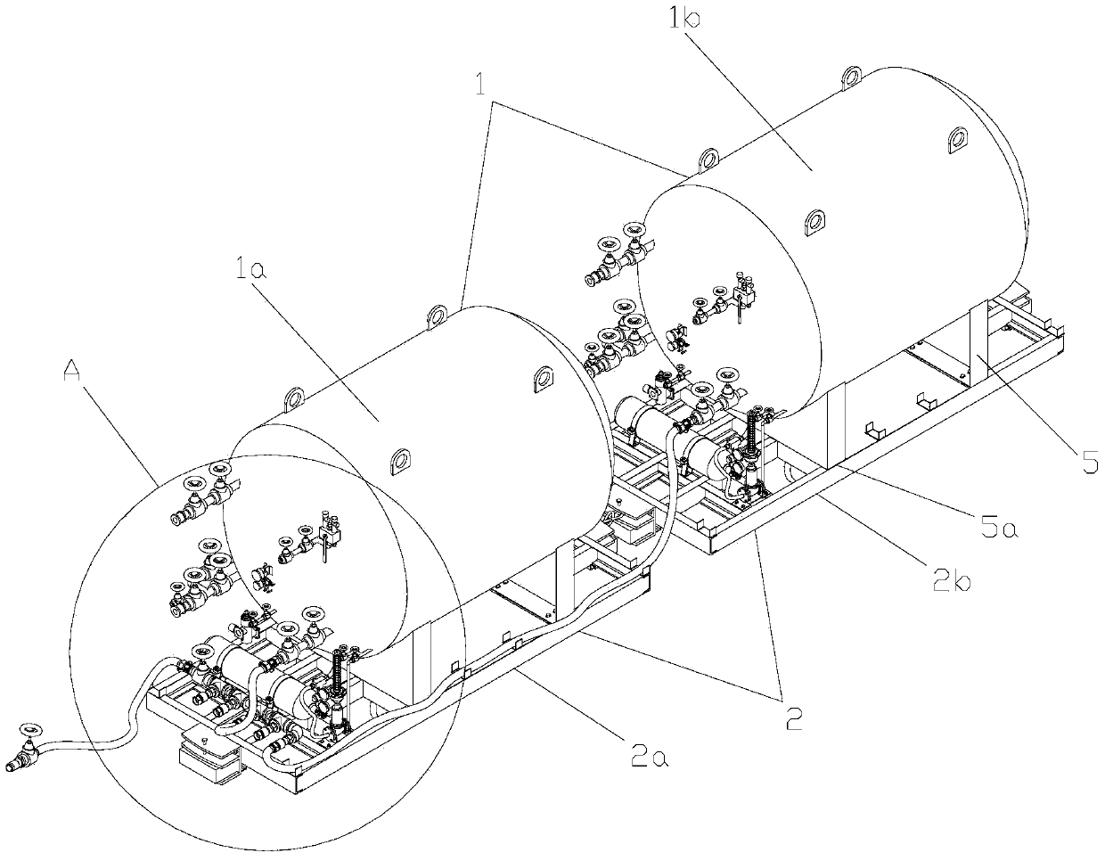
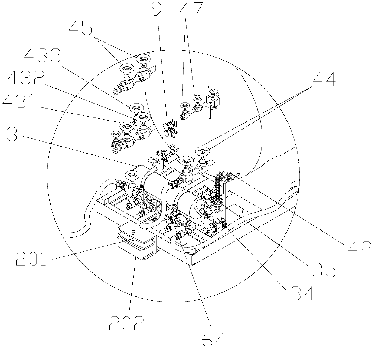
[0022] figure 1 It is a schematic diagram of the three-dimensional structure of the present invention, figure 2 for figure 1 The enlarged view at A, as shown in the figure: the liquid carbon dioxide fire extinguishing device for emergency rescue in the disaster area of ​​this embodiment includes a storage tank 1 for storing liquid carbon dioxide and a base 2 for carrying and fixing the storage tank 1. The storage tank 1 is connected with a pressure gauge, a liquid level gauge 9 and a control valve group, and also includes a pressurization control system, and the pressurization control system includes a compressed gas cylinder 31, a gas cylinder valve 32, a pressure reducer 33 and The delivery gas path used to connect with the storage tank 1; the compressed gas bottle 31 is fixed on the base 2 and filled with high-pressure gas, the control valve group includes a gas booster valve I41, and the delivery gas path includes Manually control the gas circuit, the manual control gas...


PUM


Abstract

The invention discloses a liquid carbon dioxide fire extinguishing device for emergency rescue in disaster areas. The liquid carbon dioxide fire extinguishing device comprises a liquid carbon dioxide storage tank, and a base for bearing and fixing, wherein the storage tank adopts a double-layer vacuum composite structure with a thermal insulation material, so that the heat preservation storage time of liquid carbon dioxide is prolonged; liquid discharged by a liquid discharge valve in a control valve set is conveyed to a burning area through a liquid conveying pipe, a confluence assembly and a distant conveying pipeline in sequence; the gasification spraying is realized by a nozzle; and all pipelines are inserted in corresponding joints through quick joints. The liquid carbon dioxide fire extinguishing device further comprises a boosting control system capable of effectively performing the air pressure compensation for the storage tank to prevent the ice blockage in the liquid discharging and gasification spraying process; the boosting control system consists of a compressed gas cylinder, a gas cylinder valve, a pressure reducer and a conveying gas way connected with the storage tank, which are connected in sequence; and the conveying gas way comprises manual and automatic control gas ways, and is provided with a gas conveying pipe I and a gas conveying pipe II respectively connected with a gas boosting valve I and a gas boosting valve II in the control valve set.

Description

technical field [0001] The invention relates to a fire extinguishing device, in particular to a liquid carbon dioxide fire extinguishing device for emergency rescue in disaster areas. Background technique [0002] Carbon dioxide fire extinguishing technology uses the principle that liquid carbon dioxide does not support combustion and absorbs a large amount of heat when it is gasified to achieve the purpose of cooling down and extinguishing fires. The zone space will instantly expand and gasify nearly 700 times, and absorb a large amount of heat, which can quickly suppress explosions, inert the fire zone, extinguish the fire source and cool down, and is very suitable for emergency rescue and fire fighting. The existing mobile liquid carbon dioxide fire extinguishing device generally includes a storage tank for storing liquid carbon dioxide and a base for carrying and fixing the storage tank. The storage tank is connected with a pressure gauge, a liquid level gauge and a cont...

Claims


Application Information

Patent Timeline
IPC IPC(8): A62C31/00A62C37/50
Inventor 葛亮伯志革陈阳国朱先国张广勋刘林蒋德献井婷婷王印军贾海军陈波温学雷
Owner CHINA COAL TECH ENG GRP CHONGQING RES INST
Why Eureka
Try Eureka