
Automatic light following deflection control device for improving solar thermal power generation efficiency

A technology for solar thermal power generation and control devices, applied in solar thermal power generation, solar collector controllers, solar thermal energy, etc., can solve the problems of different rotational speeds of rotating shafts, lower solar energy utilization rate, and lower power generation efficiency of solar panels, etc., to achieve The effect of guaranteeing efficiency

Inactive Publication Date: 2021-08-06
东莞市申盟光电设备有限公司
View PDF0 Cites 0 Cited by
  • Summary
  • Abstract
  • Description
  • Claims
  • Application Information

AI Technical Summary

Problems solved by technology

[0004] Aiming at the deficiencies of the prior art, the present invention provides an automatic light deflection control device for improving the efficiency of solar thermal power generation, which is equipped with two small solar panels inclined to both sides. The incident angles of the two solar panels are different, so the power generation rates of the two solar panels are different, and the rotational speeds of the driven rotating shafts are different, which leads to the deflection of the deflection device, so that the whole device is deflected to face the sunlight, ensuring the efficiency of power generation It solves the problem that the solar panels of most solar thermal power generation products on the market cannot change automatically with the change of the angle of sunlight, which leads to the reduction of the power generation efficiency of the solar panels and the utilization rate of solar energy.

Method used


Image

  • Automatic light following deflection control device for improving solar thermal power generation efficiency
  • Automatic light following deflection control device for improving solar thermal power generation efficiency
  • Automatic light following deflection control device for improving solar thermal power generation efficiency

Examples


Embodiment 1

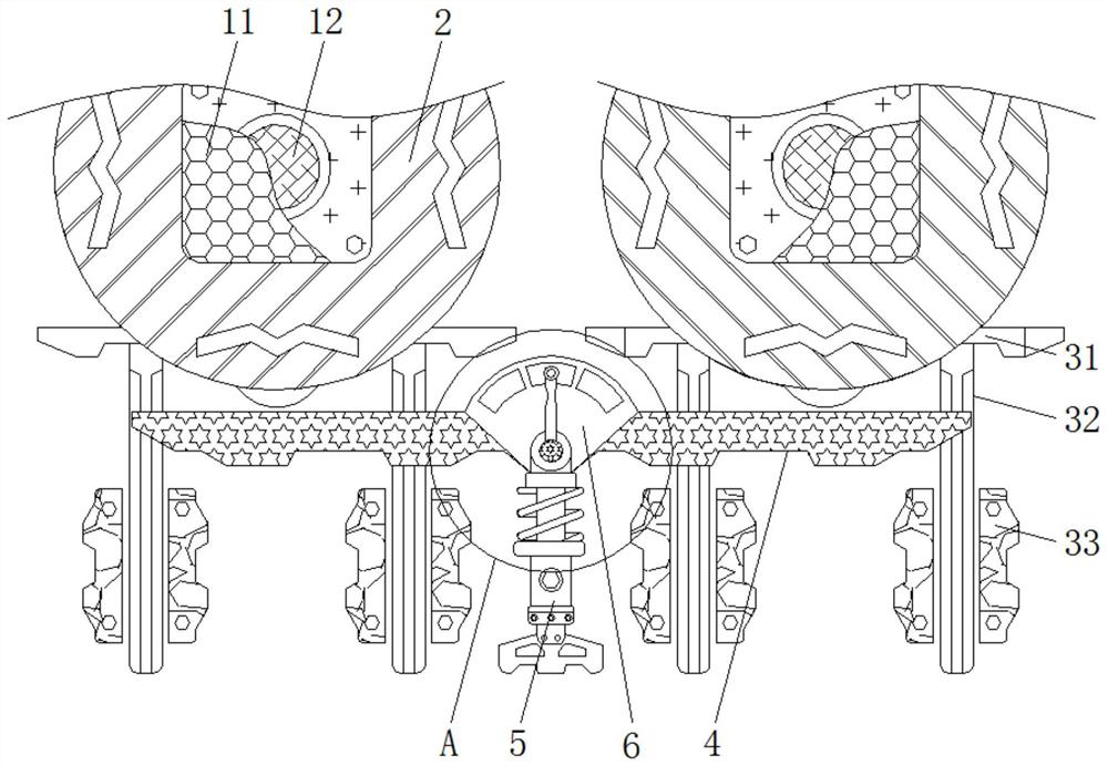
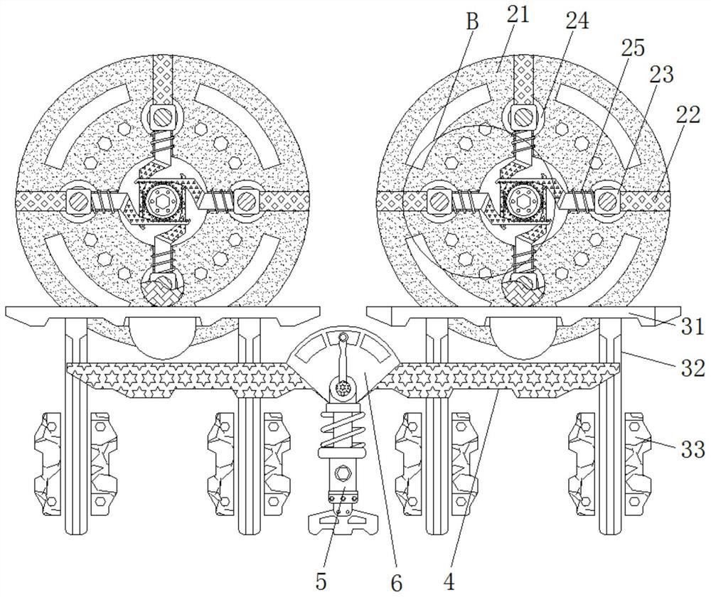
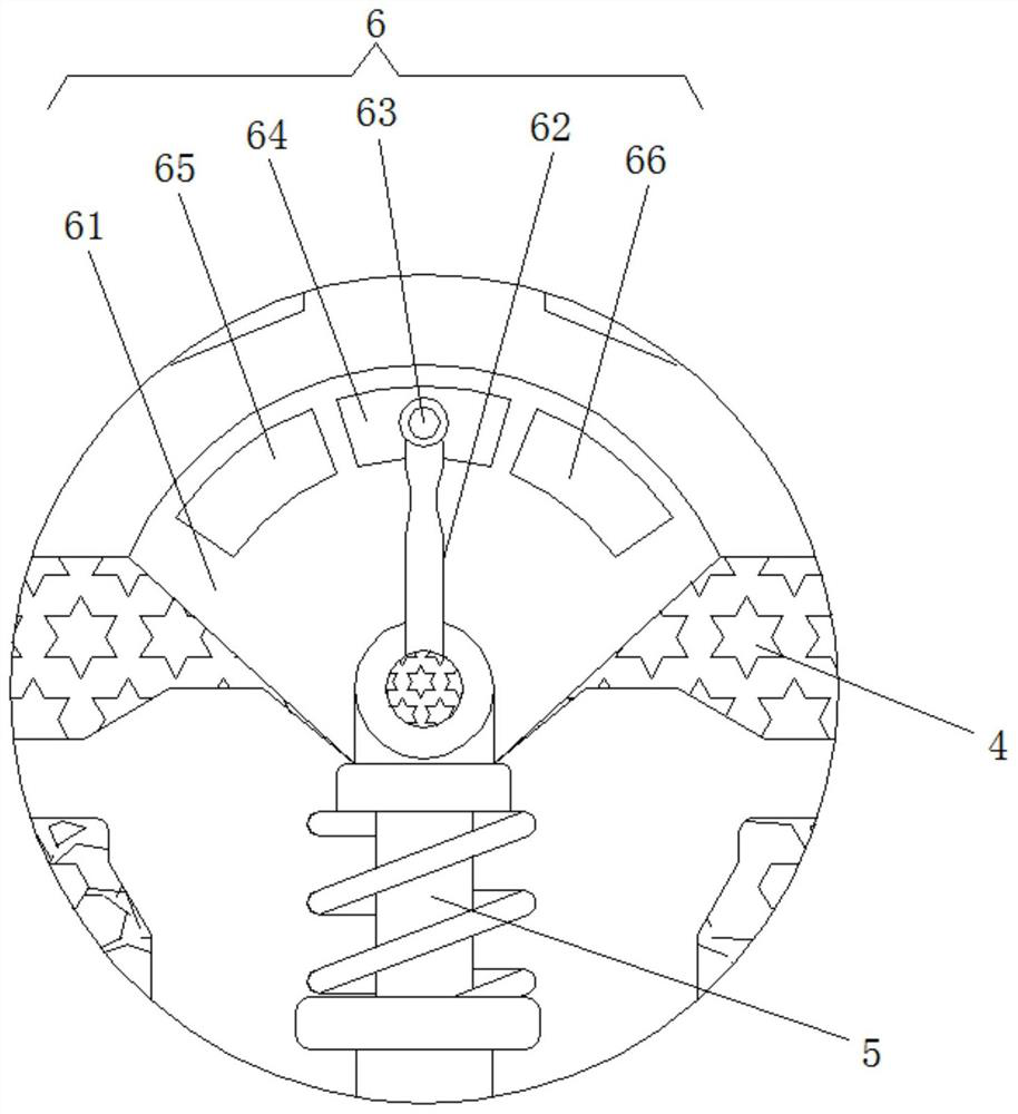
[0028] see Figure 1-4 , an automatic light deflection control device for improving the efficiency of solar thermal power generation, comprising a receiving device 1, the surface of the receiving device 1 is fixedly connected with a turntable mechanism 2, the bottom of the turntable mechanism 2 is provided with a touch device 3, and the touch device 3 A balance bar 4 is arranged on the lower side, a spring bar 5 is hinged on the surface of the balance bar 4 , and a deflection device 6 is provided at the upper end of the spring bar 5 .

[0029] The receiving device 1 includes a solar panel 11 , and a rotating shaft 12 is arranged on the rear side of the solar panel 11 .

[0030] There are two receiving devices 1, and the solar panels 11 in each receiving device 1 are electrically connected to the rotating shaft 12. The two solar panels 11 are symmetrical and inclined to the xoy plane and the orientation of the faces of the two solar panels 11 is opposite. The solar panels 11 ar...

Embodiment 2

[0032] see Figure 1-4 , an automatic light deflection control device for improving the efficiency of solar thermal power generation, comprising a receiving device 1, the surface of the receiving device 1 is fixedly connected with a turntable mechanism 2, the bottom of the turntable mechanism 2 is provided with a touch device 3, and the touch device 3 A balance bar 4 is arranged on the lower side, a spring bar 5 is hinged on the surface of the balance bar 4 , and a deflection device 6 is provided at the upper end of the spring bar 5 .

[0033] The turntable mechanism 2 includes a turntable 21, the surface of the turntable 21 is fixedly connected with a slide bar 22, the surface of the slide bar 22 is slidably connected with a slide block 23, the surface of the slide block 23 is fixedly connected with a slide block 23, and the surface of the slide block 23 rotates A trigger wheel 24 is connected, a matching spring 25 is fixedly connected to the surface of the sliding block 23 ,...

Embodiment 3

[0036] see Figure 1-4 , an automatic light deflection control device for improving the efficiency of solar thermal power generation, comprising a receiving device 1, the surface of the receiving device 1 is fixedly connected with a turntable mechanism 2, the bottom of the turntable mechanism 2 is provided with a touch device 3, and the touch device 3 A balance bar 4 is arranged on the lower side, a spring bar 5 is hinged on the surface of the balance bar 4 , and a deflection device 6 is provided at the upper end of the spring bar 5 .

[0037] The touch device 3 includes a touch plate 31 , two touch slide bars 32 are fixedly connected to the lower surface of the touch plate 31 , and a limit sliding groove 33 is slidably connected to the surface of the touch slide bar 32 .

[0038]There are two touch plates 31, the two touch plates 31 are parallel, and on a straight line, the two touch plates 31 are respectively arranged on the directly underside of the two turntable mechanisms...


PUM


Abstract

The invention relates to the technical field of solar thermal power generation products, and discloses an automatic light following deflection control device for improving solar thermal power generation efficiency. Receiving devices are included, turntable mechanisms are fixedly connected to the surfaces of the receiving devices, and touch devices are arranged at the bottoms of the turntable mechanisms. A balance rod is arranged on the lower side of each touch device, a spring rod is hinged to the surface of the balance rod, and a deflection device is arranged at the upper end of the spring rod. According to the automatic light following deflection control device for improving the solar thermal power generation efficiency, through cooperative use of the receiving devices, the deflection device and the like, the effects that two small solar panels inclining towards the two sides are utilized, when sunlight is not aligned with the device, the incident angles with the two solar panels are different, and therefore the power generation rates of the two solar panels are different, the rotating speeds of driven rotating shafts are different, so that the deflection device deflects, the whole device deflects to directly face sunlight, and the power generation efficiency is ensured are achieved.

Description

technical field [0001] The invention relates to the technical field of solar thermal power generation products, in particular to an automatic light-following deflection control device for improving the efficiency of solar thermal power generation. Background technique [0002] Now there are more and more products that use solar thermal power generation, but the solar panels of most solar thermal power generation products on the market cannot automatically change with the change of the angle of sunlight, which leads to a decrease in the power generation efficiency of the solar panel and reduces the For the utilization of solar energy, it is necessary to improve the receiving device of the solar panel and add an automatic light deflection device to ensure the efficiency of power generation. Contents of the invention [0003] (1) Solved technical problems [0004] Aiming at the deficiencies of the prior art, the present invention provides an automatic light deflection contro...

Claims


Application Information

Patent Timeline
IPC IPC(8): F24S30/425F24S50/20H02S20/30
CPCF24S30/425F24S50/20H02S20/30Y02E10/47Y02E10/50
Inventor 段小玉
Owner 东莞市申盟光电设备有限公司
Learn More