Locking device for drainage cable

A locking device and cable technology, applied in the direction of circuits, electrical components, circuit/collector components, etc., can solve the risk of arcing, cannot effectively ensure the safety of workers and power distribution equipment, and affect the connection of drainage cables and main cables Reliability and other issues to achieve the effect of reducing the risk of arcing and ensuring safety

Pending Publication Date: 2021-08-06
XIANGYANG POWER SUPPLY COMPANY OF STATE GRID HUBEI ELECTRIC POWER
View PDF0 Cites 0 Cited by
  • Summary
  • Abstract
  • Description
  • Claims
  • Application Information

AI Technical Summary

Problems solved by technology

[0002] The operation method of the high-power cable drainage in the prior art is to peel off the outer covering insulation of the main cable, connect one end of the drainage cable to the main cable, and then cover the connection between the drainage cable and the main cable with an insulating layer such as Insulation tape, because the drainage cable has a strong self-weight, if the drainage cable is not lifted or pulled, it will directly affect the reliability of the connection between the drainage cable and the main cable, and it is very likely to cause the risk of arcing, which cannot effectively guarantee the operation The safety of personnel and power distribution equipment, so the existing prior art needs a locking device for drainage cables that can effectively ensure the safety of workers and power distribution equipment

Method used


Image

  • Locking device for drainage cable
  • Locking device for drainage cable
  • Locking device for drainage cable

Examples


Embodiment Construction

[0021] The technical solutions in the embodiments of the present invention will be clearly and completely described below in conjunction with the accompanying drawings in the embodiments of the present invention. Obviously, the described embodiments are only some of the embodiments of the present invention, not all of them; based on The embodiments of the present invention and all other embodiments obtained by persons of ordinary skill in the art without making creative efforts belong to the protection scope of the present invention.

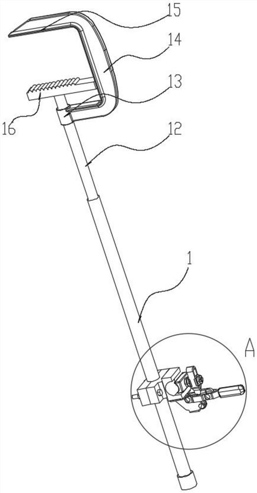
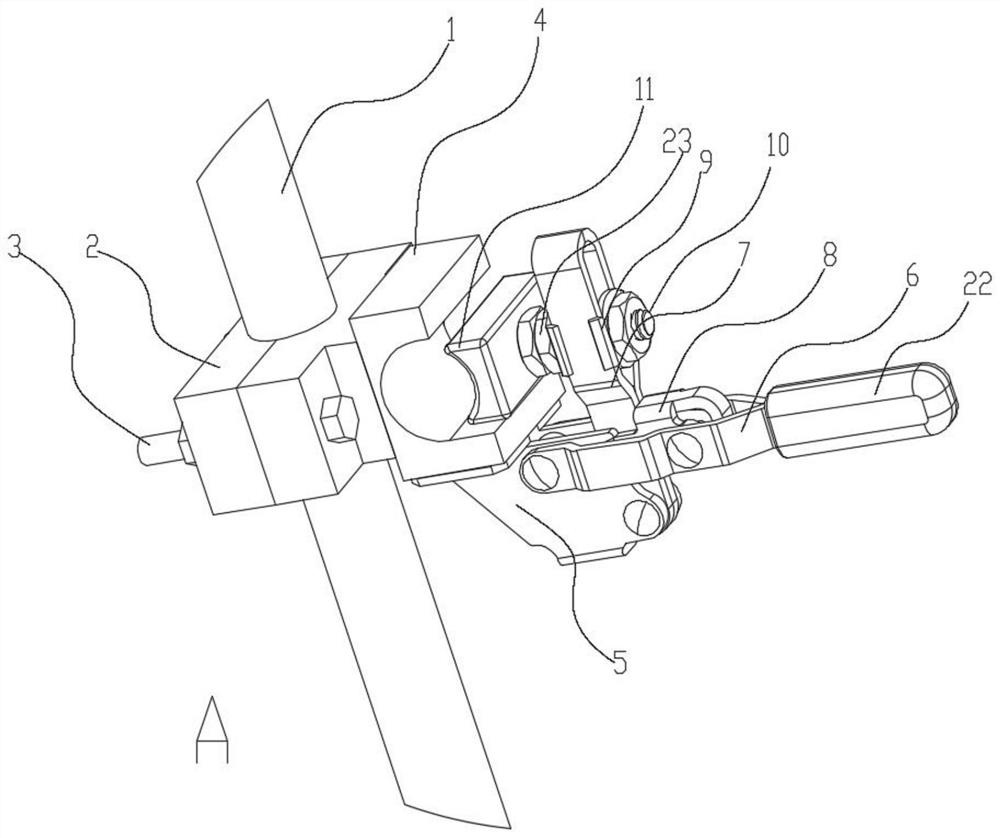
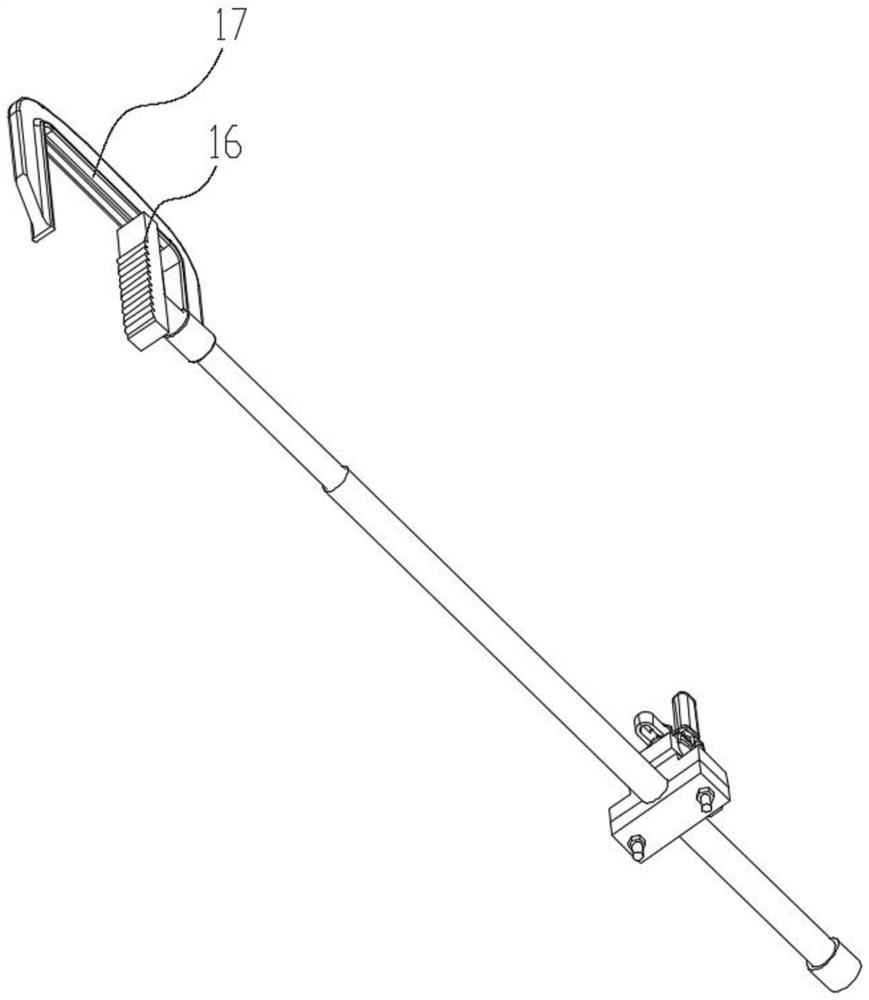
[0022] see Figure 1~5, in an embodiment of the present invention, a locking device for draining cables, including: a connecting rod 1, a locking block 2, a locking bolt 3, a fixing seat 4, a rotating seat 5, a rotating handle 6, a connecting rod 7, and a pressing block 8. Clamping tooth 9, pressure rod 10, movable block 11, screw rod 12, screw sleeve 13, connecting U frame 14, horizontal clamping rod 15, movable rod 16, slide rail 17, sliding t...


PUM


Abstract

The invention discloses a locking device for a drainage cable. The locking device comprises a connecting rod, a locking block, a locking bolt, a fixed seat, a rotating seat, a rotating handle, a connecting rod, a pressing block, clamping teeth and the like. The lower part of the connecting rod is provided with a drainage cable clamping structure formed by the locking block, the lock bolt, the fixed seat, the rotating seat, the rotating handle and the like, the upper part of the connecting rod is provided with a movable block, a screw rod, a screw sleeve, a connecting U-shaped frame, a transverse clamping rod, a movable rod, a sliding rail, sliding teeth and the like which are used for externally clamping an external attachment position. The beneficial effects of the invention are that the connection reliability between the drainage cable and the main cable is prevented from being influenced by the dead weight of the drainage cable, the arc risk is reduced, and the safety of operators and power distribution equipment is effectively ensured.

Description

technical field [0001] The invention relates to the field of electric power engineering, in particular to a locking device for drainage cables. Background technique [0002] The operation method of the high-power cable drainage in the prior art is to peel off the outer covering insulation of the main cable, connect one end of the drainage cable to the main cable, and then cover the connection between the drainage cable and the main cable with an insulating layer such as Insulation tape, because the drainage cable has a strong self-weight, if the drainage cable is not lifted or pulled, it will directly affect the reliability of the connection between the drainage cable and the main cable, and it is very likely to cause the risk of arcing, which cannot effectively guarantee the operation The safety of personnel and power distribution equipment, so the existing prior art needs a locking device for drainage cables that can effectively ensure the safety of workers and power distr...

Claims


Application Information

Patent Timeline
Patent Type & Authority Applications(China)
IPC IPC(8): H01R43/055H01R43/033
CPCH01R43/033H01R43/055
Inventor 吴一波蔡超刘利平周喆赵炜王晓明
Owner XIANGYANG POWER SUPPLY COMPANY OF STATE GRID HUBEI ELECTRIC POWER
Why Eureka
Try Eureka