Plate type floating head heat exchanger

A heat exchanger and floating head technology, which is applied in the field of plate type floating head heat exchangers, can solve the problems of out-of-synchronization of expansion, difference in thermal expansion between heat exchanger plate group and compression plate, etc., and achieve the effect of fixing and stabilizing

Inactive Publication Date: 2016-07-27
TIANJIN HUASAIER HEAT TRANSFER EQUIP
View PDF5 Cites 0 Cited by
  • Summary
  • Abstract
  • Description
  • Claims
  • Application Information

AI Technical Summary

Problems solved by technology

[0004] The purpose of the present invention is to overcome the lack of structural design of the plate heat exchanger in the prior art to eliminate thermal expansion difference, and provide a plate type floating head exchanger that adopts a floating connection to solve the thermal expansion difference and expansion asynchrony between the heat exchanger plate group and the compression plate. heater

Method used


Image

  • Plate type floating head heat exchanger
  • Plate type floating head heat exchanger
  • Plate type floating head heat exchanger

Examples


Embodiment Construction

[0021] The following will clearly and completely describe the technical solutions in the embodiments of the present invention with reference to the accompanying drawings in the embodiments of the present invention. Obviously, the described embodiments are only some, not all, embodiments of the present invention. Based on the embodiments of the present invention, all other embodiments obtained by persons of ordinary skill in the art without making creative efforts belong to the protection scope of the present invention.

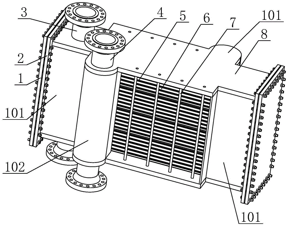
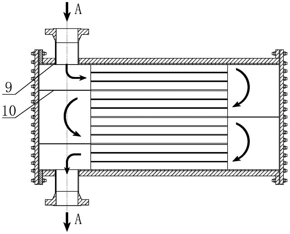
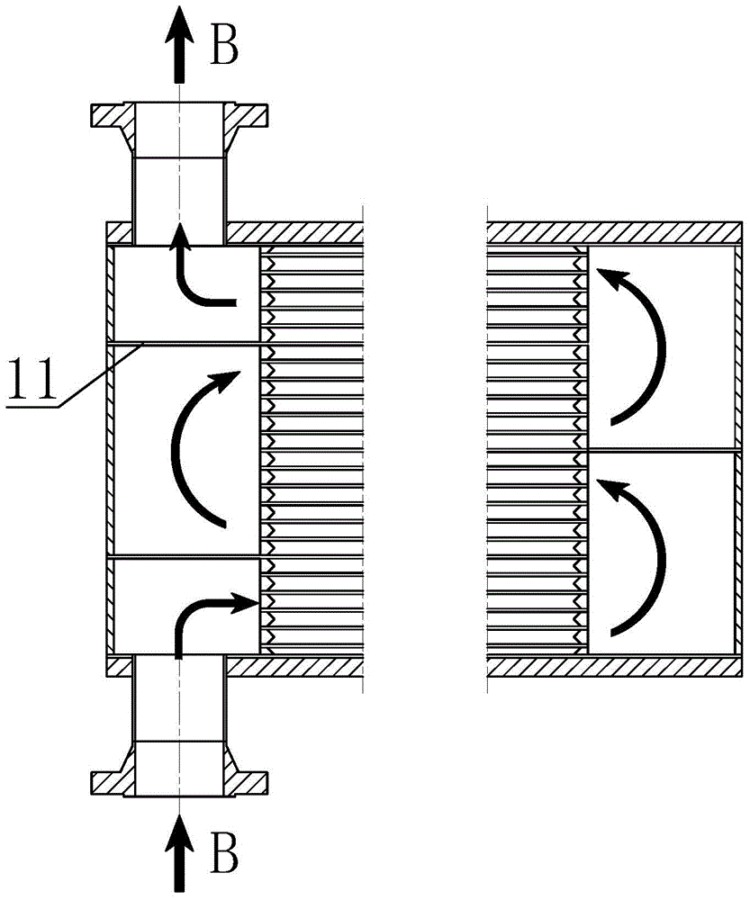
[0022] Such as Figure 1-5 The plate type floating head heat exchanger shown includes two inner tube boxes 101 arranged at both ends, two outer tube boxes 102 arranged diagonally on both sides, and a pair of inner tube boxes 101 arranged up and down. Inner tube 3, a pair of outer tubes 4 arranged on the outer tube box 102, a heat transfer plate set between the inner tube box 101 and the outer tube box 102, and the heat transfer plates are clamped by both sides...


PUM


Abstract

The invention discloses a plate type floating head heat exchanger. The plate type floating head heat exchanger comprises two inner stroke pipe boxes arranged at the two ends, two outer stroke pipe boxes diagonally arranged on the two sides, a pair of inner stroke connecting pipes arranged on the inner stroke pipe boxes up and down, a pair of outer stroke connecting pipes arranged on the outer stroke pipe boxes up and down, heat transfer plate sets arranged between the inner stroke pipe boxes and the outer stroke pipe boxes, pull rods clamping the heat transfer plate sets from the two sides, and pressing plates clamping the heat transfer plate sets from the upper end face and the lower end face. Compared with the prior art, according to the plate type floating head heat exchanger, a cushion plate for fixing a heat transfer plate assembly has a one-end extension freedom degree and a one-side extension freedom degree, and the problems that too large inner stress is generated due to the thermal expansion and chilling shrinkage difference and asynchronous deformation of the heat transfer plate sets and the pressing plates, so that the heat transfer plate set connecting reliability is affected, and fixing and sealing are in failure can be avoided. Meanwhile, the heat transfer plate sets are subjected to pressing force of the pressing plates, one side and one end of each heat transfer plate set are fixedly connected, and the heat transfer plate sets are fixed stably.

Description

technical field [0001] The invention relates to the technical field of heat exchangers, in particular to a plate type floating head heat exchanger. Background technique [0002] The floating head structure is widely used in traditional tube heat exchangers. Its unique floating tube box structure has excellent high temperature adaptability and convenient maintenance performance, and has been widely recognized. [0003] Compared with the traditional tube heat exchanger, the plate heat exchanger has the advantages of high heat transfer coefficient, compact structure, and small footprint, and is widely used in industrial and civil production. The traditional plate heat exchanger, through the internal corrugated The expansion joint eliminates the thermal expansion difference between the plate group and the compression plate, but the expansion joint is difficult to manufacture and weld, and the sealing reliability is poor, which leads to unstable operation of the equipment and dif...

Claims


Application Information

Patent Timeline
IPC IPC(8): F28D9/00F28F9/04F28F3/10
Inventor 宋秉棠赵殿金
Owner TIANJIN HUASAIER HEAT TRANSFER EQUIP
Why Eureka
Try Eureka