Photovoltaic junction box

A technology for photovoltaic junction boxes and box covers, which is applied in the field of photovoltaic junction boxes, and can solve problems such as the inability to fix the upper cover and box cover, and colloid melting

Inactive Publication Date: 2013-10-30
QC SOLAR SUZHOU CORP
View PDF4 Cites 0 Cited by
  • Summary
  • Abstract
  • Description
  • Claims
  • Application Information

AI Technical Summary

Problems solved by technology

The commonly used photovoltaic junction box at present includes a box body and a box cover that cooperates with the box body. The box cover is generally provided with a glue filling area and an upper cover for covering the glue filling area. Before the glue filling, Generally, it is necessary to use the top cover to cover the glue filling area first, and then pour glue through the glue hole on the top cover. After gluing, it generally takes a certain amount of time for the colloid to harden to fix the upper cover and the box cover. At the same time, because the colloid used for dispensing has a slightly higher melting point, when the temperature is too high when the glue is poured, it is easy to melt the dispensing colloid. Therefore, the upper cover and the box cover cannot be fixed

Method used


Image

  • Photovoltaic junction box
  • Photovoltaic junction box
  • Photovoltaic junction box

Examples


Embodiment Construction

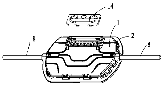
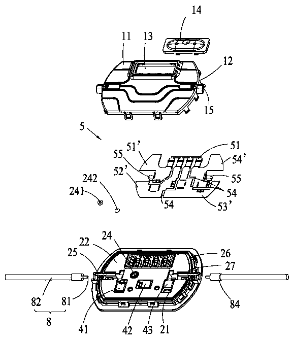
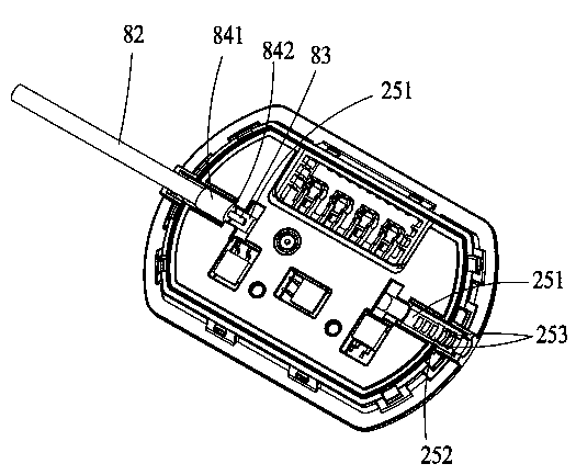
[0020] See figure 1 , a photovoltaic junction box, including a box body 2, a box cover 1 cooperating with the box body 2, a copper plate 5 arranged in the box body 2, four busbars (not shown), and two electrically connected copper plates 5 Cables, and cables 8 are used to lead the cables 8 from the outside of the photovoltaic junction box into the cable grooves in the photovoltaic junction box box. Part of the cables 8 are accommodated in the cable grooves. The metal connecting ends 51 are electrically connected one-to-one.

[0021] See Figure 4 , 5 The box cover 1 includes a cover body 11, a side plate 12 extending downward from the edge of the cover body 11, and an upper cover 14 snap-fitted to the cover body 11. The cover body 11 has a penetrating The glue filling area 13 of the cover body 11 and the upper cover plate 14 are used to cover the glue filling area 13 . In this embodiment, the buckle connection between the cover body 11 and the upper cover plate 14 adopts t...


PUM


Abstract

The invention relates to a photovoltaic junction box which comprises a box body and a box cover matched with the box body, wherein the box cover comprises a cover body portion and a side plate portion formed by the edge of the cover body portion in a downward extending mode, a glue filling area penetrating through the cover body portion is arranged on the cover body portion, the box cover further comprises an upper cover plate used for shielding the glue filling area, and the upper cover plate is connected with the cover body portion in a buckled mode. Compared with the prior art, the photovoltaic junction box has the advantages that the purpose of rapid installation of the upper cover plate can be achieved through buckled connection, therefore a subsequent glue filling process can be carried out without waiting, and meanwhile the buckled connection can guarantee the fact that the connection reliability of the upper connection cannot be influenced due to the surrounding environment after the upper cover plate is installed.

Description

technical field [0001] The invention relates to a photovoltaic junction box. Background technique [0002] Inexhaustible solar energy is being favored by more and more people. Solar photovoltaic power generation has been included in the new energy development and utilization plan by many countries, and the application volume is expanding year by year. The commonly used photovoltaic junction box at present includes a box body and a box cover that cooperates with the box body. The box cover is generally provided with a glue filling area and an upper cover for covering the glue filling area. Before the glue filling, Generally, it is necessary to use the top cover to cover the glue filling area first, and then pour glue through the glue hole on the top cover. After gluing, it generally takes a certain amount of time for the colloid to harden to fix the upper cover and the box cover. At the same time, because the colloid used for dispensing has a slightly higher melting point, ...

Claims


Application Information

Patent Timeline
Patent Type & Authority Applications(China)
IPC IPC(8): H01L31/048
CPCY02E10/50
Inventor 段正刚
Owner QC SOLAR SUZHOU CORP
Why Eureka
Try Eureka