
Rotary piston engine having optimized internal cooling of intake air

A rotary piston, internal cooling technology, used in rotary piston engines, rotary or oscillating piston engines, internal combustion piston engines, etc., can solve problems such as maximum engine air volume limitation, insufficient engine cooling, limiting engine maximum power and durability, etc.

Pending Publication Date: 2021-08-06
保尔亨里克沃尔夫
View PDF6 Cites 0 Cited by
  • Summary
  • Abstract
  • Description
  • Claims
  • Application Information

AI Technical Summary

Problems solved by technology

[0010] The disadvantage of the prior art is that the air available for cooling is directly dependent on the throttle opening and with the throttle fully open it is limited by the maximum amount of air the engine can handle
As a result, the cooling of the engine may be insufficient, especially under full load and rapid load changes, which limits the maximum power and durability of the engine

Method used


Image

  • Rotary piston engine having optimized internal cooling of intake air
  • Rotary piston engine having optimized internal cooling of intake air
  • Rotary piston engine having optimized internal cooling of intake air

Examples


Embodiment Construction

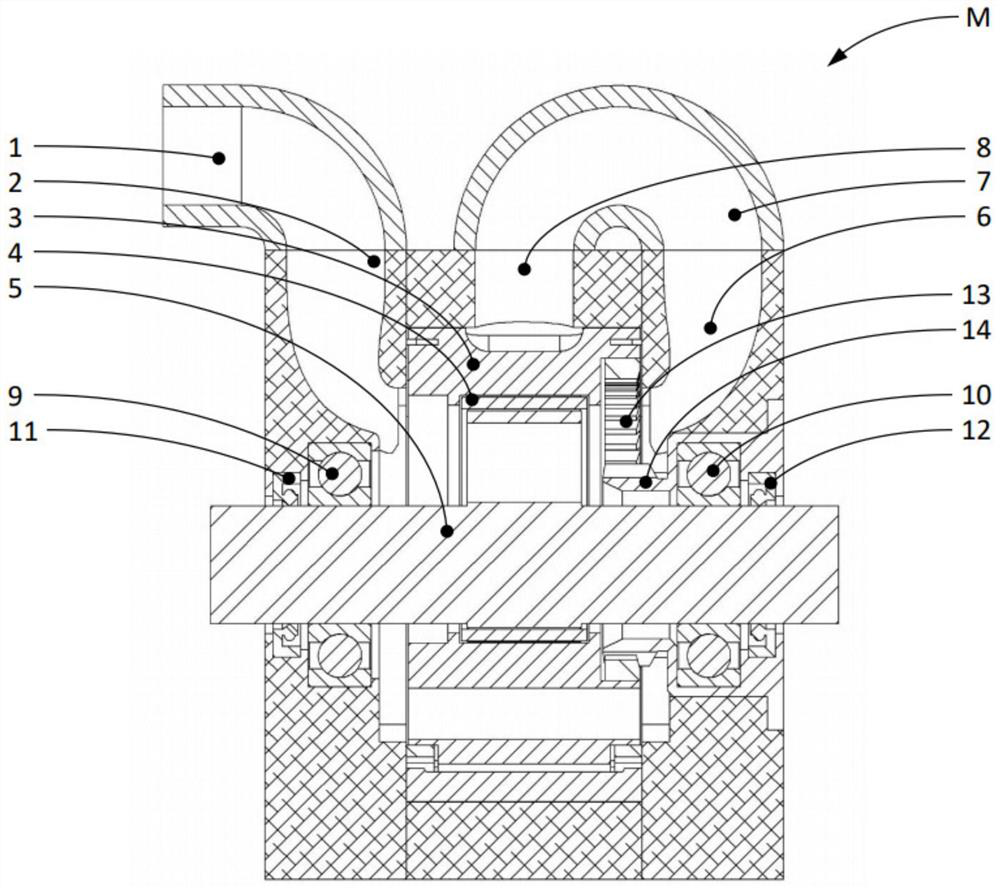
[0038] figure 1 Used to explain the components and shows a rotary piston engine in epicycloidal design with internal cooling (M) of the intake air in a sectional view through the central axis and the inlet channel. The figure shows the intake manifold (1), the side plate connected with the intake manifold (2), the rotor (3), the eccentric shaft (5), and the gap between the rotor (3) and the eccentric shaft (5). So-called main bearing (4), second side plate (6), trochoid (8) and bridge (7) as connection between side plate (6) and trochoid (8). Further shown are the side bearings (9, 10) of the eccentric shaft (5), the shaft seal rings (11, 12) for sealing the eccentric shaft (5), and the gears (13) and side plates in the rotor (3) Overview of the corresponding fixed gear (14) in (6).

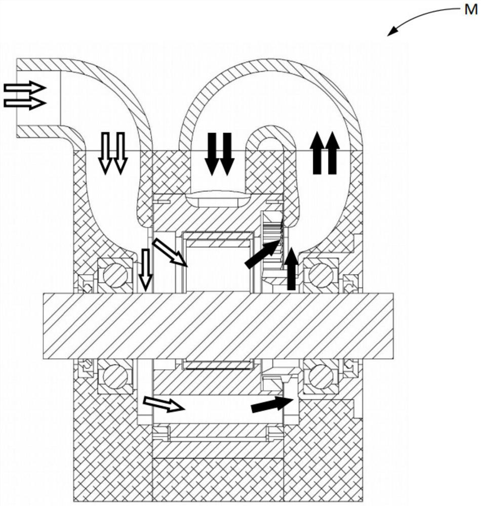
[0039] figure 2 based on figure 1 The sectional view of shows with arrows how the intake air flows through a rotary piston engine (M) of epicycloidal design with internal cooling of the inta...


PUM


Abstract

The invention relates to a rotary piston engine having internal cooling of intake air and supercharging (EM), characterized in that at least one blocking member (V) through which boost pressure can escape is provided in the connection between components that are to be cooled and the inlet into the working chamber.

Description

technical field [0001] The invention relates to a rotary piston engine. In practice, rotary piston engines are mainly characterized by a long (short) swivel design with a double-lobe epicycloid shape on the inner casing surface, as so-called Wankel engines. In this type of engine, a central casing with a two-lobed long (short) swivel inner profile (also known as a trochoid) and casing sections that laterally close the trochoid on each side (also known as side plate) forms a working space in which a rotary piston (also referred to as a rotor) rotates, the rotary piston having a convex triangular shape when viewed in a sectional view perpendicular to the central axis of the engine. The rotor drives the eccentric part of the shaft (also called the eccentric shaft) on which the rotor is mounted. The central axis of the eccentric shaft lies on the central axis of the motor, in the origin of the trochoidal profile. The guidance of the rotor in the working space is usually achieve...

Claims


Application Information

Patent Timeline
IPC IPC(8): F01C1/22F01C21/04F01C21/06F01C21/18
CPCF02B55/06F02B55/12F01C1/22F01C21/06F01C21/18F01C21/04F01C21/183F02B53/14Y02T10/12B01D45/12F01M11/08F02B29/02F02B29/0406F02B37/16
Inventor 保尔·亨里克·沃尔夫保罗·安德里亚斯·沃尔夫
Owner 保尔亨里克沃尔夫
Learn More