Tensioning device facilitating installation of synchronous belt and chain

A technology of tensioning device and synchronous belt, applied in chain/belt transmission, transportation and packaging, vehicle gearbox, etc., can solve problems such as troublesome connection process, difficult synchronous belt installation, low efficiency, etc., to improve installation efficiency, Guarantee the effect of performance

Pending Publication Date: 2021-08-17
ZHEJIANG ENZE VEHICLE CO LTD
View PDF0 Cites 0 Cited by
  • Summary
  • Abstract
  • Description
  • Claims
  • Application Information

AI Technical Summary

Problems solved by technology

[0003] The rear wheels are erected in the rear end of the frame through the rear wheel shaft, so the driven wheels are also in the rear end of the frame. If the timing belt is to be connected to the driving wheel and the driven wheel, the timing belt itself is in the form of a ring , the driven wheel is in the rear end of the frame, and it is extremely difficult to complete the installation of the timing belt without any gaps that can be snapped in. It can only be completed in the state of being in a chain. Firstly, one end of the chain is inserted into the rear end of the frame, then around the driven wheel, then pulled forward and around the driving wheel, and finally the two ends of the chain are connected by a linker. It is troublesome, and it is difficult to grasp the tension degree of the chain when it cooperates with the driving wheel and the driving wheel. The distance between the axis of the driving wheel and the axis of the driven wheel of a traditional bicycle is constant. Once the chain is in a loose state after installation, it will The chain needs to be disassembled and reconnected again, which makes the entire process of installing the chain extremely troublesome and extremely inefficient

Method used


Image

  • Tensioning device facilitating installation of synchronous belt and chain
  • Tensioning device facilitating installation of synchronous belt and chain
  • Tensioning device facilitating installation of synchronous belt and chain

Examples


Embodiment Construction

[0022] Below in conjunction with accompanying drawing and specific embodiment the present invention will be described in further detail:

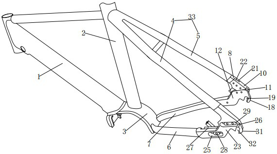
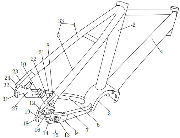
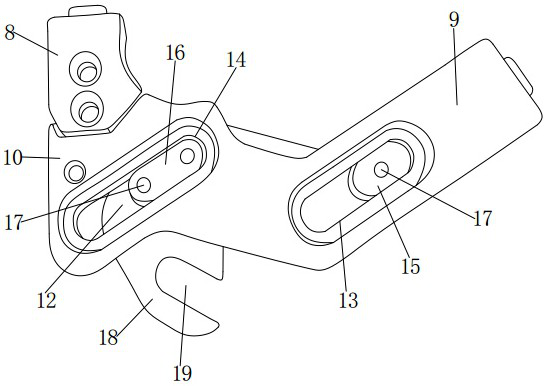
[0023] see Figure 1 to Figure 6 , the present invention provides a tensioning device for synchronous belt and chain installation, including a vehicle frame 1, a column 2 located at the center of the vehicle frame 1, and a wheel cover 3 located at the lower end of the column 2. The left upper support arm 4 and the right upper support arm 5 are arranged on the side; the left and right sides behind the wheel cover 3 are provided with a left lower support arm 6 below the left upper support arm 4 and a right lower support arm 7 below the right upper support arm 5; The rear end of the upper left support arm 4 and the rear end of the upper right support arm 5 are all inclined downward; the upper left support arm 4, the lower left support arm 6 and the column 2 form a triangle; the upper right support arm 5 and the lower right support arm 7 is en...


PUM


Abstract

The invention discloses a tensioning device facilitating installation of a synchronous belt and a chain, which comprises a frame, a stand column arranged in the center of the frame and a wheel cover arranged at the lower end of the stand column, wherein a left upper supporting arm and a right upper supporting arm are arranged on the left side and the right side of the rear portion of the upper end of the stand column; a left lower supporting arm located below the left upper supporting arm and a right lower supporting arm located below the right upper supporting arm are arranged on the left side and the right side of the rear portion of the wheel cover; the rear end of the left upper supporting arm and the rear end of the right upper supporting arm incline downwards; a triangle is defined by the upper left supporting arm, the lower left supporting arm and the stand column; a triangle is defined by the right upper supporting arm, the right lower supporting arm and the stand column; and a fixing block is arranged at the rear end of the right upper supporting arm. According to the tensioning device facilitating installation of the synchronous belt and the chain, installation of the chain can be rapidly completed, the tensioning degree of the chain can be rapidly adjusted according to actual needs, and the chain can be kept in a tensioned state.

Description

technical field [0001] The invention relates to a tensioning device, in particular to a tensioning device which facilitates the installation of synchronous belts and chains. Background technique [0002] A bicycle refers to a small land vehicle with two or three wheels, while an electric bicycle is a kind of bicycle. Regardless of whether it is a bicycle or an electric bicycle, the center of the frame is equipped with a driving wheel, which is erected on the center side of the rear wheel on the rear side of the frame. There is a driven wheel on the side, and the driving wheel and the driven wheel are connected by a synchronous belt or a chain. When the rider drives the driving wheel to rotate by stepping on the bicycle pedal, under the action of the synchronous belt or chain, the driven wheel will be rotated. Rotate, thereby driving the rear wheel to rotate to realize the forward movement of the bicycle. [0003] The rear wheels are erected in the rear end of the frame thro...

Claims


Application Information

Patent Timeline
Patent Type & Authority Applications(China)
IPC IPC(8): B62M9/16
CPCB62M9/16
Inventor 李恩斌
Owner ZHEJIANG ENZE VEHICLE CO LTD
Why Eureka
Try Eureka