

a children's stroller
A technology of children's stroller and stroller frame, which is applied in the direction of children's carriage/baby carriage, multi-axis children's carriage/cradle car, children's carriage/cradle car accessories, etc. It can solve the problem that the wheels are not fixed, easy to move, and the wheels are easy to dump And other problems, to achieve the effect of folding operation
- Summary
- Abstract
- Description
- Claims
- Application Information
AI Technical Summary
Problems solved by technology
Method used
Image

Examples
Embodiment 1
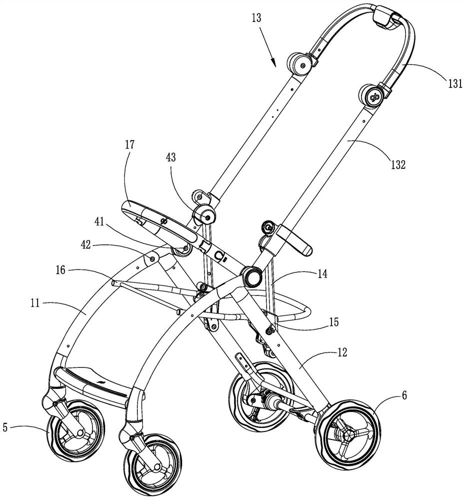
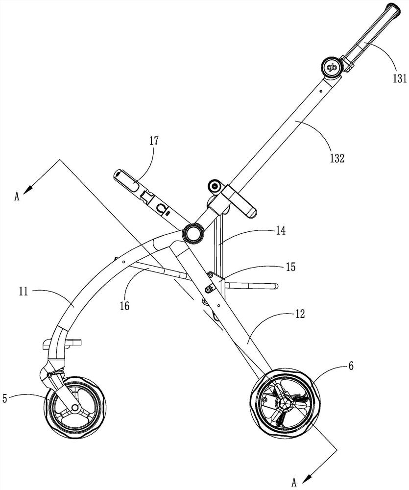
[0034] like Figure 1~Figure 9 As shown, the stroller of the present invention includes a stroller frame having an unfolded and collapsed state, a plurality of wheels disposed on the bottom of the stroller frame, a locking mechanism for locking the stroller frame in the unfolded state, and Brake mechanism for braking part of the wheel.
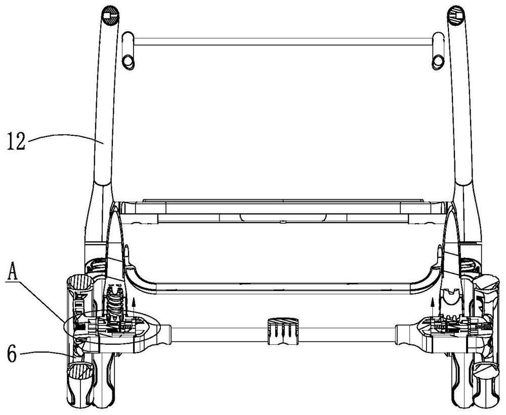
[0035] The wheels include a front wheel 5 provided at the bottom front of the cart frame and a rear wheel 6 provided at the bottom rear of the cart frame. The brake mechanism can brake the front wheel 5 or the rear wheel 6 . In this embodiment, the brake mechanism brakes the rear wheel 6 . The braking mechanism has braking and releasing states. When the braking mechanism is in the braking state, the rear wheel 6 is braked and cannot be rotated; when the braking mechanism is in the releasing braking state, the rear wheel 6 can be rotated, thereby changing the position of the stroller.
[0036] The stroller of this embodiment can be folded und...
Embodiment 2
[0054] like Figure 10 and Figure 11 As shown, in this embodiment, the driving mechanism can drive the braking mechanism to brake during the folding process of the cart frame, that is, the traction cable 31 can be stretched during the folding process of the cart frame, and the other end of the traction cable 31 is fixed It is arranged on a part that relatively rotates and / or slides during the folding process of the cart frame. Specifically, in the frame structure of the cart given in Embodiment 1, the other end of the traction cable 31 is fixedly arranged on the lower push rod 132 and is located at the rotational connection between the lower push rod 132 and the rear bracket 12 .
[0055] In this embodiment, the unlocking method of the locking mechanism can also be the same as that in the first embodiment. After the locking mechanism is unlocked, under the action of its own gravity, the push rod assembly 13 rotates downward and moves closer to the rear bracket 12. When the ...
Embodiment 3
[0057] like Figure 12 and Figure 13 As shown in the figure, in this embodiment, the traction cable 31 can be stretched during the folding process of the cart frame as in the second embodiment, and the other end of the traction cable 31 is fixedly arranged to undergo relative rotation and / or sliding on a part. Specifically, in the frame structure of the cart given in Embodiment 1, the other end of the traction cable 31 is fixedly arranged on the upright pole 14 .
[0058] In this embodiment, the unlocking method of the locking mechanism can also be the same as that in the first embodiment. After the locking mechanism is unlocked, under the action of its own gravity, the push rod assembly 13 rotates downward and moves closer to the rear bracket 12, so that the vertical rod 14 rotates relative to the push rod assembly 13 and slides downward relative to the sliding member 15, and the vertical rod 14 rotates and When sliding down, the traction cable 31 is stretched, and it p...
PUM
 Abstract
Description
Claims
Application Information