
Auxiliary equipment for eliminating water hammer effect in high-end equipment manufacturing

A water hammer effect and auxiliary equipment technology, applied in mechanical equipment, pipes/pipe joints/pipe fittings, pipe components, etc., can solve the problems of slow buffering efficiency of water hammer force, inability to wrap the pipeline, decompression, damage, etc., to avoid the effect of destruction

Pending Publication Date: 2021-08-20
杭州昀蓓贸易有限公司
View PDF0 Cites 1 Cited by
  • Summary
  • Abstract
  • Description
  • Claims
  • Application Information

AI Technical Summary

Problems solved by technology

[0002] Water treatment equipment is always inseparable from pipelines in daily life. Water hammer effect is common in pipelines when valves are closed. Water hammer effect means that inside water pipes, the inner wall of the pipe is smooth and water flows freely. The valve and the pipe wall, mainly because the valve will generate a pressure. Because the pipe wall is smooth, the subsequent water flow will quickly reach the maximum under the action of inertia and cause damage. This is the so-called "water hammer effect" in hydraulics. In the prior art, a piston buffer mechanism is installed on the side of the pipe close to the valve to buffer the force of the water flow impacting the surrounding pipe wall. However, due to the limited arrangement and quantity of the pistons, it is impossible to form a wrap around the entire circumferential surface of the pipe. decompression, resulting in slow buffering efficiency for water hammer force and unsatisfactory decompression effect; therefore, we propose a high-end equipment manufacturing auxiliary equipment to eliminate water hammer effect

Method used


Image

  • Auxiliary equipment for eliminating water hammer effect in high-end equipment manufacturing
  • Auxiliary equipment for eliminating water hammer effect in high-end equipment manufacturing
  • Auxiliary equipment for eliminating water hammer effect in high-end equipment manufacturing

Examples


Embodiment Construction

[0024] The following will clearly and completely describe the technical solutions in the embodiments of the present invention with reference to the accompanying drawings in the embodiments of the present invention. Obviously, the described embodiments are only some, not all, embodiments of the present invention. Based on the embodiments of the present invention, all other embodiments obtained by persons of ordinary skill in the art without making creative efforts belong to the protection scope of the present invention.

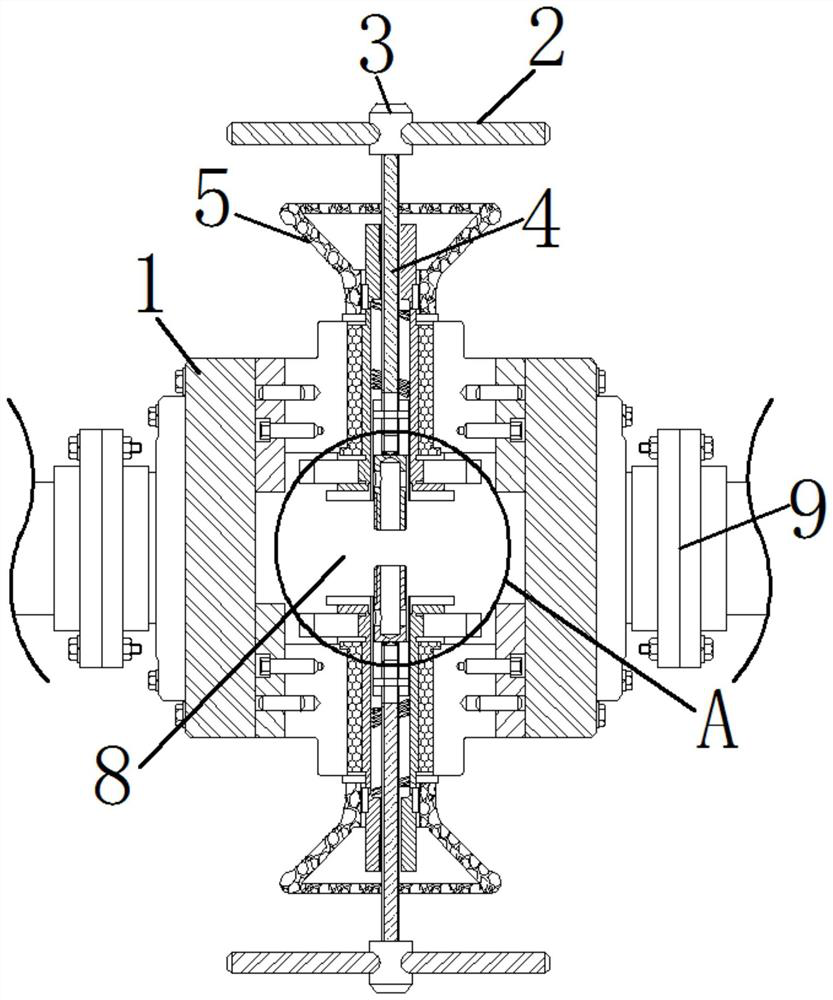
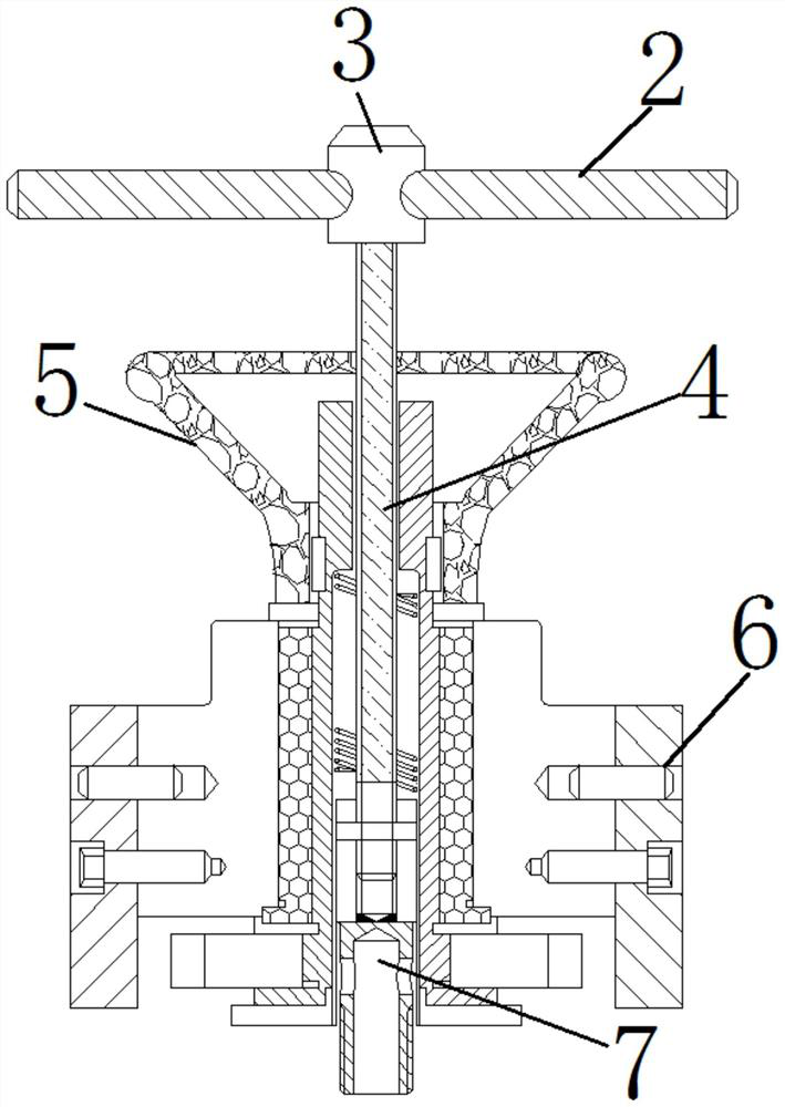
[0025] see Figure 1-7 , an auxiliary equipment for high-end equipment manufacturing to eliminate the water hammer effect, including a device main body 1, a twisting bolt 2 is installed on the inside of the device body 1, and an installation block 3 is fixedly installed on the inner side of the twisting bolt 2, and the bottom of the installation block 3 A torsion bar 4 is movably connected, a support frame 5 is fixedly installed on the outside of the torsion b...


PUM


Abstract

The invention relates to the technical field of intelligent equipment, and discloses auxiliary equipment for eliminating water hammer effect in high-end equipment manufacturing. The equipment comprises an equipment main body, a twisting bolt is movably mounted in the equipment main body, a mounting block is fixedly mounted at the inner side of the twisting bolt, and a torsion rod is movably connected below the mounting block. A supporting frame is fixedly installed at the outer side of the torsion rod, a valve body outer wall is fixedly installed in the equipment main body, an inserting block is fixedly connected to the top end of a rod body of the torsion rod, and a valve cavity is formed in the equipment main body. According to the auxiliary equipment for eliminating the water hammer effect in high-end equipment manufacturing, a V-shaped block impacts a connecting spring towards the inner side, the connecting spring then impacts a mounting plate towards the inner side, the mounting plate then drives a bearing shaft center to synchronously press a compression spring towards the inner side, the compression spring immediately compresses a buffering air bag, the buffering air bag is pressed to deform, meanwhile, impact force is buffered, and the water hammer effect is prevented from damaging a water flow pipeline.

Description

technical field [0001] The invention relates to the technical field of intelligent equipment, in particular to an auxiliary equipment for eliminating the water hammer effect in high-end equipment manufacturing. Background technique [0002] Water treatment equipment is always inseparable from pipelines in daily life. Water hammer effect is common in pipelines when valves are closed. Water hammer effect means that inside water pipes, the inner wall of the pipe is smooth and water flows freely. The valve and the pipe wall, mainly because the valve will generate a pressure. Because the pipe wall is smooth, the subsequent water flow will quickly reach the maximum under the action of inertia and cause damage. This is the so-called "water hammer effect" in hydraulics. In the prior art, a piston buffer mechanism is installed on the side of the pipe close to the valve to buffer the force of the water flow impacting the surrounding pipe wall. However, due to the limited arrangement a...

Claims


Application Information

Patent Timeline
IPC IPC(8): F16L55/055F16L55/045F16L55/033
CPCF16L55/033F16L55/045F16L55/055
Inventor 王晓燕
Owner 杭州昀蓓贸易有限公司
Learn More