Signal-processing circuit

A signal processing circuit and signal path technology, applied in the direction of measuring electrical variables, voltage/current isolation, measuring current/voltage, etc., to achieve the effect of increasing safety and reducing workload

Pending Publication Date: 2021-08-20
EGSTON SYST ELECTRONICS EGGENBURG
View PDF1 Cites 0 Cited by
  • Summary
  • Abstract
  • Description
  • Claims
  • Application Information

AI Technical Summary

Problems solved by technology

This will make it possible to correlate the damage caused by lightning with the current generated

Method used


Image

  • Signal-processing circuit
  • Signal-processing circuit
  • Signal-processing circuit

Examples


Embodiment Construction

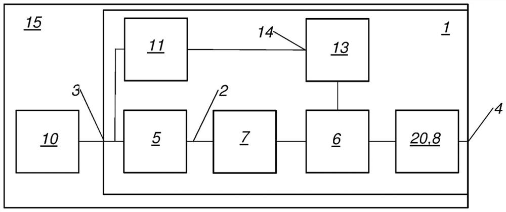
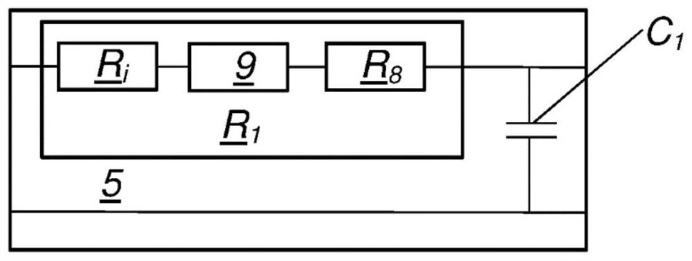
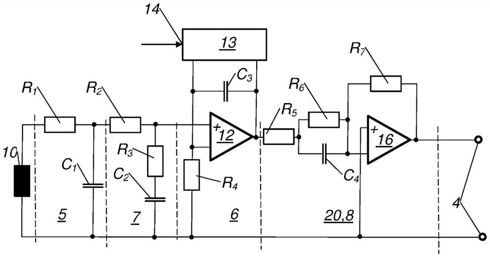
[0018] figure 1 and image 3 Each shows a current measuring system 15 with a signal processing circuit 1 with at least one signal path 2 between an input 3 and an output 4 of the signal processing circuit 1 , wherein the signal path 2 has a first passive integrating element 5 and an active integrating device 6, wherein the active integrator 6 is designed as a non-inverting active integrator 6, wherein the first passive integrating element 5 and the active integrator 6 are connected in series in the signal path 2, wherein the signal path 2 also includes a second Two passive integrating elements 7 and differentiating elements 20 .

[0019] This means that currents with a wide dynamic range and signal components with high edge steepnesses or high slew rates (in particular greater than 10 kA / μs) can also be accurately detected and measured by means of the current measuring coil 10 . This prevents signal components with high slew rates from causing malfunctions at the active inte...


PUM


Abstract

The invention relates to a signal-processing circuit (1), comprising at least one signal path (2) between an input (3) and an output (4) of the signal-processing circuit (1), wherein: the signal path (2) has a first passive integrating element (5) and an active integrator (6); the active integrator (6) is designed as a non-inverting active integrator (6); the first passive integrating element (5) and the active integrator (6) are connected in series within the signal path (2). According to the invention, the signal path (2) additionally has a second passive integrating element (7) and a differentiating element (20).

Description

technical field [0001] The invention relates to a signal processing circuit according to the preamble of claim 1 . Background technique [0002] It is known to use coils as sensors for current measurement. In particular air-core coils or so-called Rogowski coils have proven to be advantageous. The Rogowski coil outputs the difference between the measured currents as a voltage. It is therefore necessary to process such measurement signals by means of subsequent integration. [0003] Both active and passive circuits for integrating signals are known. Furthermore, it is known to combine active integrators with passive integrating elements for detecting or measuring currents with high dynamics. It has been shown that the use of the well-known inverting integrator-operational amplifier circuit to form an active integrator has considerable disadvantages when signals with large voltage swings are applied to the input of such a circuit. [0004] From US 6 614 218B1 (Ray) and pu...

Claims


Application Information

Patent Timeline
Patent Type & Authority Applications(China)
IPC IPC(8): G01R15/18
CPCG01R15/181G01R19/00G01R19/0046
Inventor 史帝芬·崔森罗曼·贾米
Owner EGSTON SYST ELECTRONICS EGGENBURG
Why Eureka
Try Eureka