Full-automatic forming equipment for electronic component shell

A technology for molding equipment and electronic components, which is applied in the field of fully automatic molding equipment for electronic component shells, can solve the problems of poor shearing effect and low injection molding efficiency, achieve convenient adsorption of parts, improve injection molding quality, increase shearing efficiency and The effect of clip quality

Pending Publication Date: 2021-08-27
无锡威孚工程塑料有限公司
View PDF5 Cites 1 Cited by
  • Summary
  • Abstract
  • Description
  • Claims
  • Application Information

AI Technical Summary

Problems solved by technology

[0004] In view of the shortcomings of the above-mentioned prior art, the purpose of the present invention is to provide a fully automatic molding equipment for electronic component shells to solve the problems of low injection molding efficiency and poor shearing effect of products in the prior art

Method used


Image

  • Full-automatic forming equipment for electronic component shell
  • Full-automatic forming equipment for electronic component shell
  • Full-automatic forming equipment for electronic component shell

Examples


Embodiment Construction

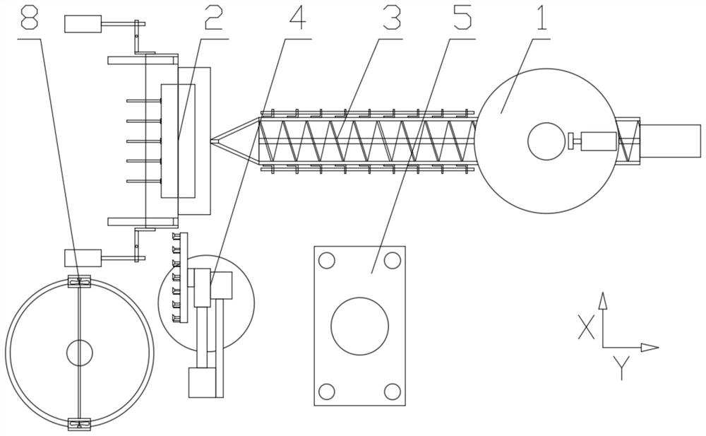
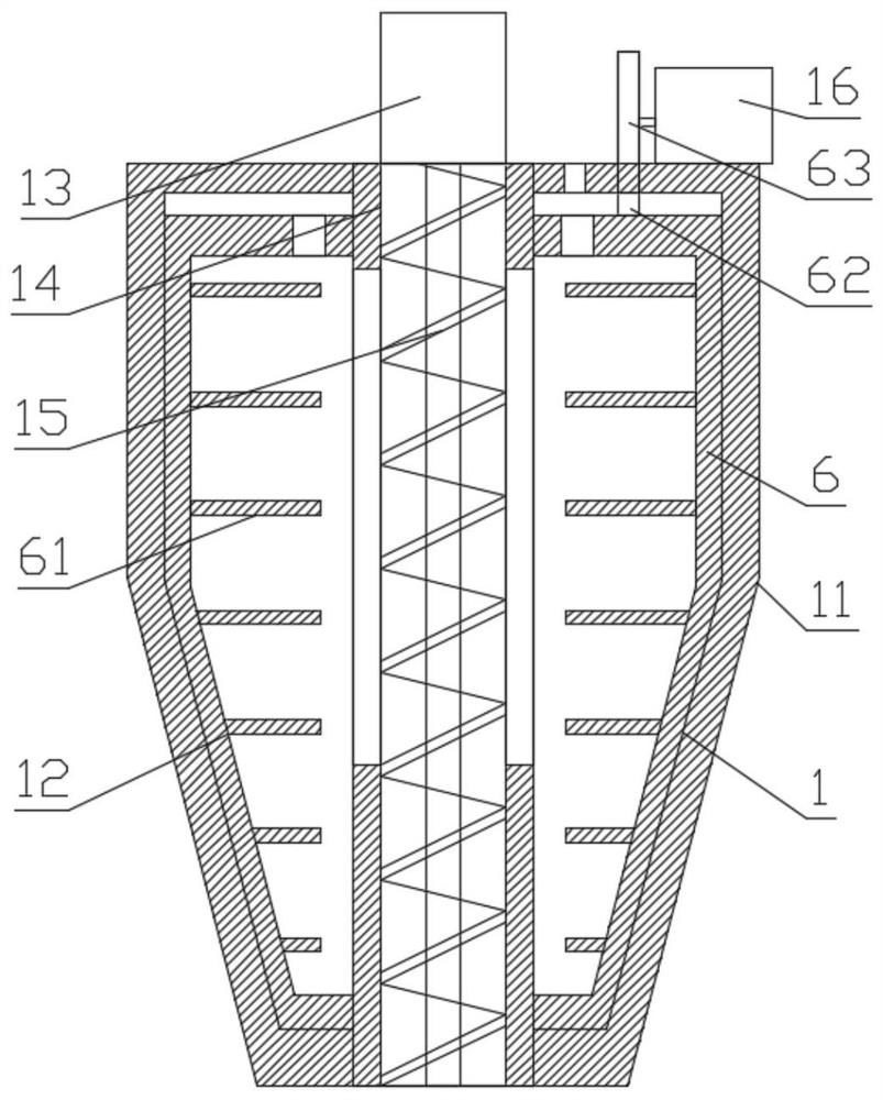
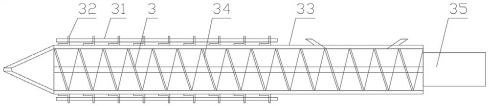
[0026] In order to make the purpose, technical solution and advantages of the present invention clearer, the device proposed by the present invention will be further described in detail below in conjunction with the accompanying drawings and specific embodiments. The advantages and features of the present invention will become clearer from the following description. It should be noted that the drawings are in a very simplified form and all use imprecise scales, which are only used to facilitate and clearly assist the purpose of illustrating the embodiments of the present invention. In order to make the objects, features and advantages of the present invention more comprehensible, please refer to the accompanying drawings. It should be noted that the structures, proportions, sizes, etc. shown in the drawings attached to this specification are only used to match the content disclosed in the specification, for those who are familiar with this technology to understand and read, an...


PUM


Abstract

The invention relates to full-automatic forming equipment for an electronic element shell. The full-automatic forming equipment is characterized by comprising a material mixing mechanism for mixing materials, a mold mechanism for part forming, an injection molding mechanism for injecting a mixture into the mold mechanism, a clamping mechanism for clamping and moving parts and a punching mechanism for shearing the parts; the material mixing mechanism communicates with an inlet of the injection molding mechanism; the mold mechanism communicates with an outlet of the injection molding mechanism; and the clamping mechanism is arranged between the mold mechanism and the punching mechanism. The problems that in an existing scheme, the injection molding efficiency of products is low, and the shearing effect is poor are solved.

Description

technical field [0001] The invention relates to the field of molding equipment, in particular to a fully automatic molding equipment for electronic component shells. Background technique [0002] The working principle of injection molding equipment is similar to the syringe used for injection. It uses the thrust of the screw to inject the plasticized molten plastic into the closed mold cavity, and obtains the finished product after curing. The process of injection molding The plastic raw materials used in the molding process are various, and the types and forms of mold designs are also varied. In addition, the operator's familiarity with specific injection molding equipment and the differences in operating skills and practical experience among workers are also different. At the same time, the objective environment will also vary with the seasons, and these objective and subjective conditions jointly determine the occurrence of defects in injection molded products. The injec...

Claims


Application Information

Patent Timeline
IPC IPC(8): B29C45/18B29C45/47B29C45/38B29C45/42B29C45/73B29B7/14B29L31/34
CPCB29C45/18B29C45/47B29C45/382B29C45/42B29C45/7337B29B7/14B29C2045/4241B29L2031/3481
Inventor 陈胜越袁斯朗
Owner 无锡威孚工程塑料有限公司
Why Eureka
Try Eureka