A charging power supply test load and system

A charging power supply and load testing technology, which is applied in power supply testing, improvement of basic electrical components, etc., can solve problems such as inability to realize fine adjustment of back pressure and residual voltage on energy storage capacitors, achieve precise residual voltage control and ensure accuracy Effect

Active Publication Date: 2021-10-29
成都歆慎科技有限公司
View PDF15 Cites 0 Cited by
  • Summary
  • Abstract
  • Description
  • Claims
  • Application Information

AI Technical Summary

Problems solved by technology

[0004] The purpose of the present invention is to overcome the problem that the existing technology cannot realize the fine adjustment of the back pressure and residual voltage on the energy storage capacitor, and provides a charging power supply test load and system

Method used


Image

  • A charging power supply test load and system
  • A charging power supply test load and system
  • A charging power supply test load and system

Examples


Embodiment 1

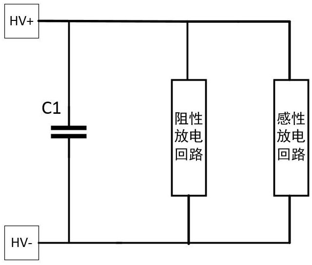
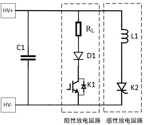
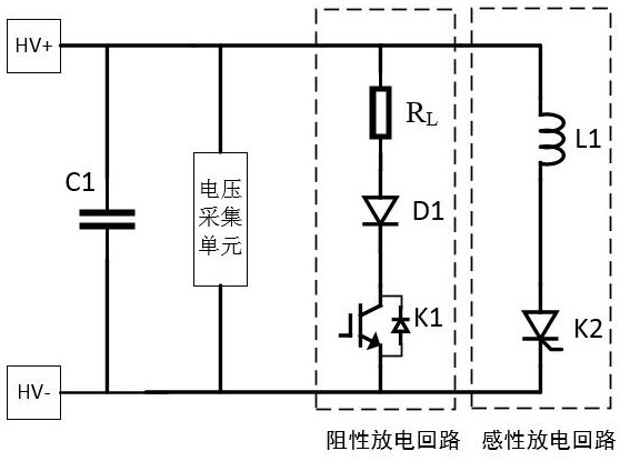
[0039] like figure 1As shown in Example 1, a charging power supply test load specifically includes an energy storage capacitor connected in parallel with the charging power supply output, and the resistive discharge circuit connected in parallel with the energy storage capacitor, and connected in parallel with the energy storage capacitor. Inductive discharge loop. Specifically, the resistive discharge loop is to discharge the charging power supply by the resistive load, and the sensing discharge circuit is to discharge the charging power source by the sensing load; the present invention can be applied to a plurality of charging power supply load characteristics test scenarios, including not The load test scene of the charging power supply of the energy recovery circuit and the load test scene of the charging power supply with the energy recovery circuit. When the test load of the present invention is applied to a load test of a charging power source without an energy recovery cir...


PUM


Abstract

The invention discloses a charging power supply test load and system, belonging to the technical field of power supply test loads, comprising an energy storage capacitor connected in parallel with the output end of the charging power supply, a resistive discharge circuit and an inductive discharge circuit connected in parallel with the energy storage capacitor. The combination of the resistive discharge circuit and the inductive discharge circuit of the present invention can simulate the process of discharging the energy storage capacitor to zero and then recharging, and then accurately simulate various load characteristics of the charging power supply, and realize the energy storage capacitor by controlling the working time of the resistive discharge circuit. Back pressure and residual pressure adjustment, so as to truly restore various working condition parameters of the charging power supply.

Description

Technical field [0001] The present invention relates to the field of power test load, and more particularly to a charging power supply test load and system. Background technique [0002] A pulse charging power source (hereinafter referred to as a charging power source) for pulse power system storage capacitance (hereinafter referred to as a charging power) is generally charged at a certain repetition frequency, and the charging power supply is first charged in a single working cycle, and then the energy is The capacitor will discharge the load in a short period of time, which will then enter the next work cycle. The load will release all of the energy of all capacitances in a short time. Since the load is generally inductive, some energy returns are partially energy return, and the energy recovery circuit is recovered through the energy recovery circuit to the energy storage capacitor, so the end of one cycle ends. After that, when the next cycle begins, the energy storage capaci...

Claims


Application Information

Patent Timeline
Patent Type & Authority Patents(China)
IPC IPC(8): G01R31/40G01R1/20
CPCG01R1/20G01R31/40
Inventor 徐远灿
Owner 成都歆慎科技有限公司
Why Eureka
Try Eureka