A multi-mode satellite antenna pan-tilt control device

A technology for a control device and a multi-mode satellite, applied in the field of satellite antennas, can solve the problems of easy loosening, plugs affecting the overall use of the control device, easy entry of dust and impurities into the interior of the control device, etc., so as to avoid easy falling off.

Active Publication Date: 2022-08-02
亚太卫星宽带通信(深圳)有限公司
View PDF4 Cites 0 Cited by
  • Summary
  • Abstract
  • Description
  • Claims
  • Application Information

AI Technical Summary

Problems solved by technology

[0002] With the advancement of satellite communication technology, its application scope is becoming wider and wider. As the main component of satellite communication, the types of ground satellite receiving equipment are also increasing. Multi-mode satellite antenna pan-tilt is one of them, and multi-mode satellite When the antenna pan / tilt is used, a control device is required to regulate it; in view of the technical problems in the above-mentioned control device, according to the patent No. CN201521029069.3, a multi-mode satellite antenna pan / tilt control device, this multi-mode satellite antenna cloud Platform control device, at least one sub-satellite antenna folding arm is arranged at the junction of the frame and the omni-directional pan-tilt, and the sub-satellite antenna adjustment pan-tilt is arranged at one end of the sub-satellite antenna folding arm far away from the omni-directional pan-tilt, and the sub-satellite antenna adjusts the pan-tilt A secondary satellite antenna receiving device is fixed on the platform; the control device is usually electrically connected with the antenna pan / tilt through wires, and a plug needs to be embedded inside the control device to facilitate connection with other electrical structures, and the antenna pan / tilt is installed outdoors for a long time. The internal plug of the control device is easy to loose after being embedded for a long time. After the plug is loose, it will affect the overall use of the control device, and at the same time, dust and impurities can easily enter the inside of the control device.

Method used


Image

  • A multi-mode satellite antenna pan-tilt control device
  • A multi-mode satellite antenna pan-tilt control device
  • A multi-mode satellite antenna pan-tilt control device

Examples


Embodiment 1

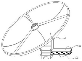
[0025] Embodiment 1: a multi-mode satellite antenna pan-tilt control device, comprising an antenna pan-tilt 1, a device box 101 is mounted on the side of the antenna pan-tilt 1, and a socket 102 is embedded in the inner side of the device box 101. The inner side of the 102 is inlaid with a rubber strip 103, and the inner side of the socket 102 is provided with a transmission mechanism that can automatically limit the position of the plug;

[0026] Wherein: the rubber strips 103 are arranged in an “L” shape, the rubber strips 103 are arranged at the upper and lower ends of the socket 102 , the device box 101 is electrically connected with the antenna head 1 , and the plug is embedded in the socket 102 . , the plug is squeezed to one side of the rubber strip 103, and the rubber strip 103 drives the transmission mechanism to limit the upper and lower ends of the plug to prevent the plug from falling off;

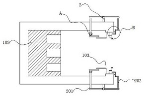
[0027] The transmission mechanism includes a lever frame 2, a sliding fram...

Embodiment 2

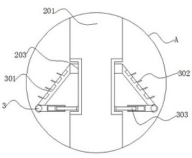
[0034] Reference manual attached Figure 4 , 5 And 6, the difference between Embodiment 2 and Embodiment 1 is that the transmission mechanism includes a connecting rod 4, a turntable 401, a shaft center 402, an extension ring 403, a bump 404, a through shaft 5, a limit frame 501, a tooth piece 502 and a limiter Position block 503, the connecting rod 4 rotates on one side of the swing frame 202, one side of the turntable 401 rotates on one end of the connecting rod 4, the axis 402 runs through the interior of the turntable 401, and the extension ring 403 swings on the other side of the turntable 401. At one end, the convex block 404 is embedded in one end of the extension ring 403, and one end of the convex block 404 is rotatably fitted with a tooth piece 502. One end of the tooth piece 502 swings a limit frame 501, and a through shaft 5 is rotated inside the limit frame 501 to limit the The position block 503 is inlaid on the other end of the limit frame 501;

[0035]The tur...


PUM


Abstract

The invention provides a multi-mode satellite antenna pan-tilt control device, comprising an antenna pan-tilt, a device box body is mounted on the side of the antenna pan-tilt, a plug socket is embedded in the inner side of the device box body, and a rubber strip is embedded in the inner side of the socket socket , The inner side of the socket is provided with a transmission mechanism that can automatically limit the position of the plug. The transmission mechanism includes a lever frame, a sliding frame, a swing frame, a track, a rotating shaft, a sealing frame, a baffle and a telescopic rod. When the turntable swings, the extension ring is driven to move Swing horizontally, the bump drives the limiter to swing as a whole through the tooth piece, so that the limiter can swing around the through shaft. When the limiter swings, it drives the limiter to limit and fix the two ends of the plug, so that the The device can automatically limit the plug when the plug is embedded inside, to avoid the situation that the plug is easy to fall off after long-term use, and can use the limiter as a whole to prevent dust from entering the interior of the socket through the gap between the plug and the socket. .

Description

technical field [0001] The invention relates to the technical field of satellite antennas, in particular to a multi-mode satellite antenna pan-tilt control device. Background technique [0002] With the advancement of satellite communication technology, its application range is becoming more and more extensive. As the main component of communication with satellites, the types of ground satellite receiving equipment are also increasing. Multi-mode satellite antenna pan / tilt is one of them. When the antenna pan / tilt is used, a control device is required for regulation; in view of the technical problems existing in the above-mentioned control device, according to the patent number CN201521029069.3, a multi-mode satellite antenna pan-tilt control device, the multi-mode satellite antenna cloud At least one sub-satellite antenna folding arm is arranged at the connection between the rack and the omni-directional pan / tilt, and one end of the far omni-directional pan / tilt on the sub-...

Claims


Application Information

Patent Timeline
Patent Type & Authority Patents(China)
IPC IPC(8): G05D3/12
CPCG05D3/12
Inventor 庞立新魏昌宁闫文凯段毅冯建元
Owner 亚太卫星宽带通信(深圳)有限公司
Why Eureka
Try Eureka