

Conveniently controlled metal plating fixing device
A fixing device and metal plating technology, applied in the electrolysis process, electrolysis components, etc., can solve the problems of difficult fixing and low practicability, and achieve the effect of convenient use, flexibility and high applicability
- Summary
- Abstract
- Description
- Claims
- Application Information
AI Technical Summary
Problems solved by technology
Method used
Image

Examples
Embodiment Construction
[0023] The following will clearly and completely describe the technical solutions in the embodiments of the present invention with reference to the accompanying drawings in the embodiments of the present invention. Obviously, the described embodiments are only some, not all, embodiments of the present invention. Based on the embodiments of the present invention, all other embodiments obtained by persons of ordinary skill in the art without making creative efforts belong to the protection scope of the present invention.
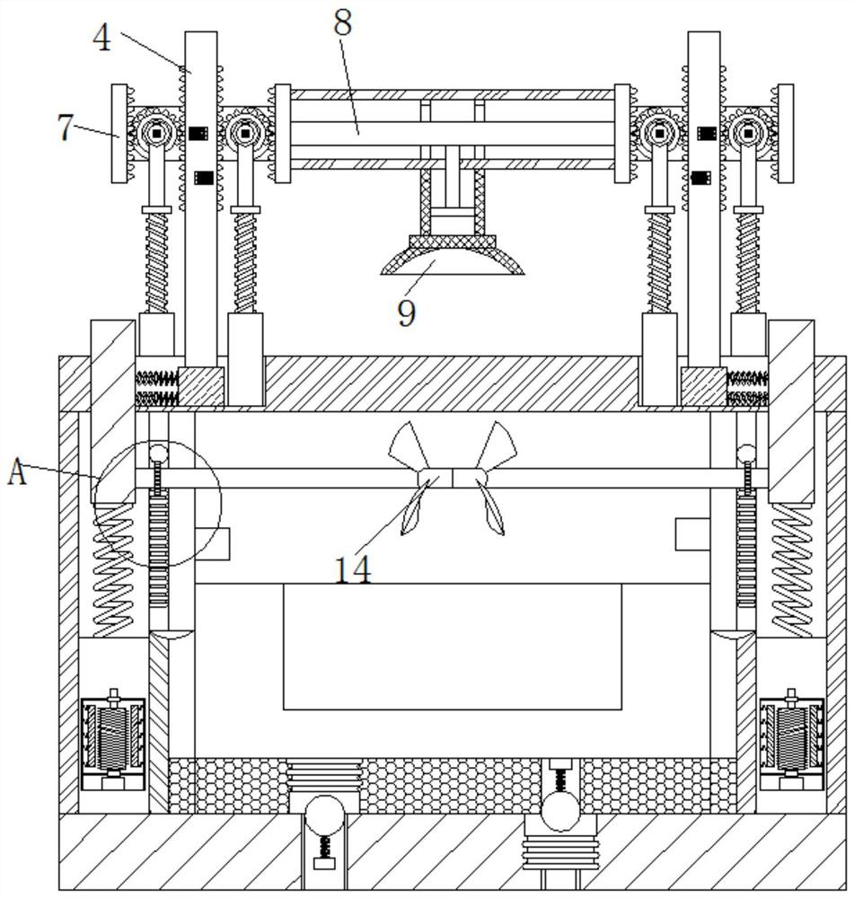
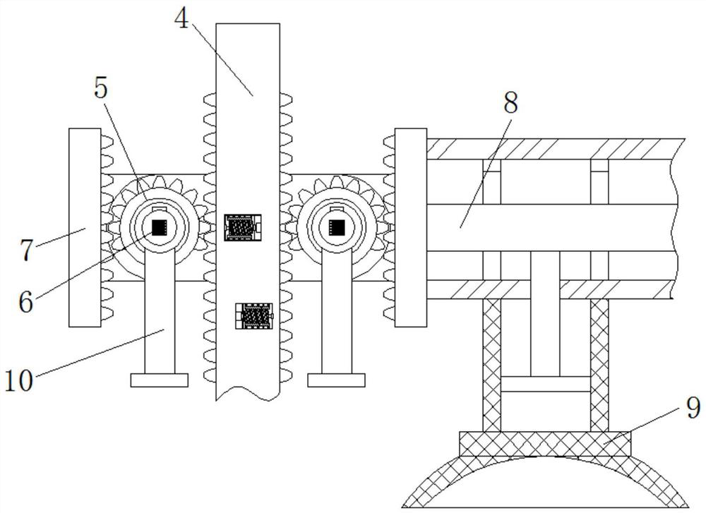
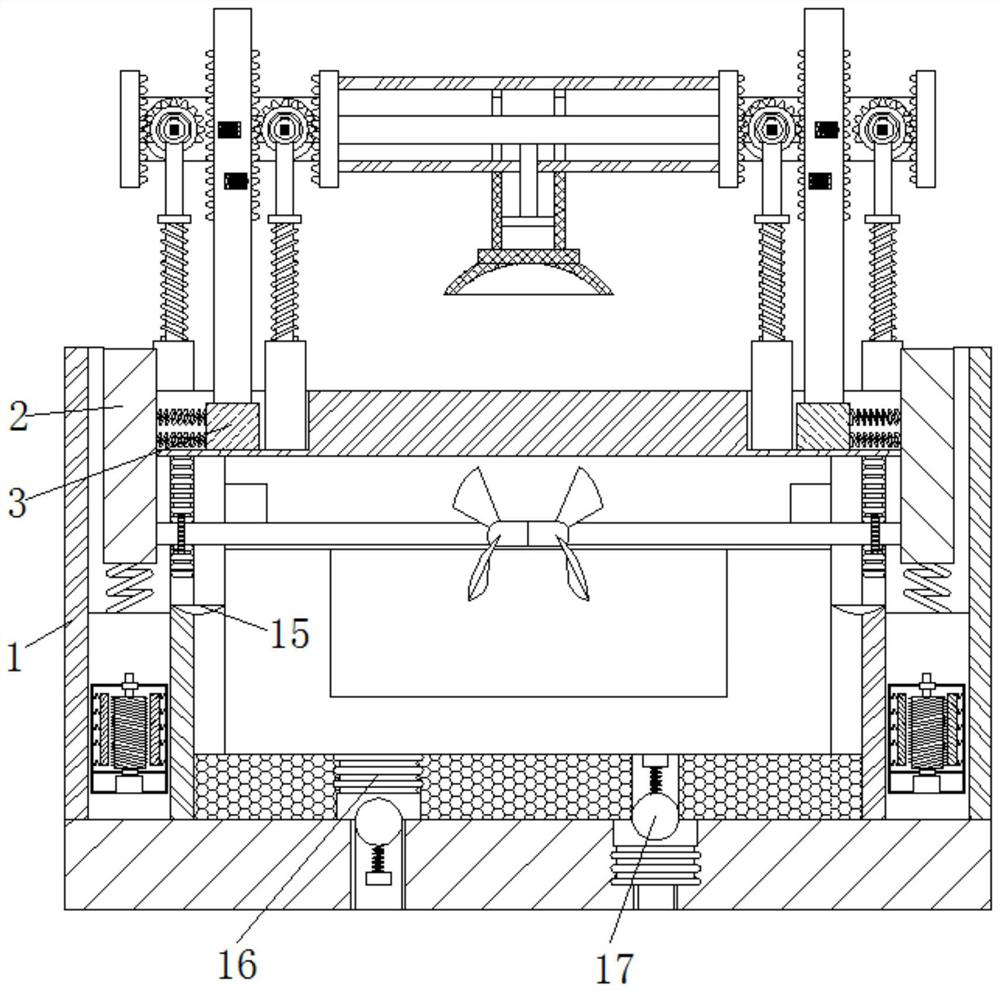
[0024] see Figure 1-4 , a metal plating fixing device that is easy to control, includes a casing 1, an electrolytic cell is arranged inside the casing 1, a soft magnetic block 2 is slidably connected to the inside of the casing 1, and a sliding block 3 is movably connected to the top of the soft magnetic block 2, The inside of the sliding block 3 is fixedly connected with the first connecting rod 4, and the middle part of the first connecting rod 4 is provide...
PUM
 Abstract
Description
Claims
Application Information