

Relay assembly for LED lamp
A technology of LED lights and relays, applied in the direction of relays, electromagnetic relays, detailed information of electromagnetic relays, etc., can solve the problems of relay plug falling off, relay and switch connection falling off, relay unable to switch circuit control, etc., to avoid the effect of easy falling off
- Summary
- Abstract
- Description
- Claims
- Application Information
AI Technical Summary
Problems solved by technology
Method used
Image

Examples
Embodiment 1
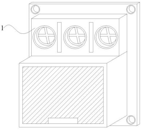
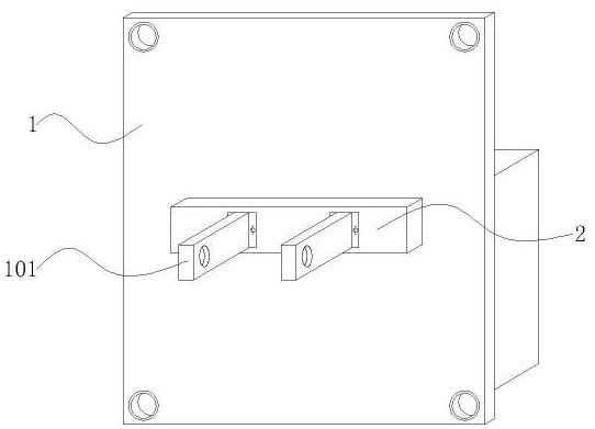
[0034] Embodiment 1: An LED lamp relay assembly, including a relay 1, a plug 101 is installed on the back of the relay 1, a base 2 is installed on the side of the plug 101 close to the relay 1, and a transmission mechanism that can be automatically reinforced is provided on the inner side of the base 2;
[0035] Wherein: the plug 101 is fitted and connected with the LED light switch, the plug 101 is a metal plug, and the relay 1 is mounted and fitted with the LED light switch through the plug;
[0036] The base 2 is arranged between the plug 101 and the relay 1. When the plug 101 is embedded inside the LED light switch, the transmission mechanism automatically increases the tightness of the connection between the plug 101 and the LED light switch by using the extrusion force;
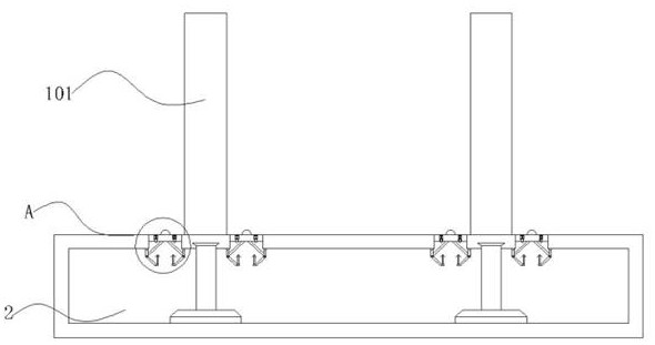
[0037] The transmission mechanism includes a bump 201, a slider 202, a slide rail 203, a connecting rod 3, a lever frame 301, a swing arm 302 and an extruding frame 303. The slider 202 slides on the insi...
Embodiment 2
[0047] Embodiment 2: with reference to instruction manual Figure 6 and 7 It can be seen that the difference between Embodiment 2 and Embodiment 1 is that the transmission mechanism includes an extension rod 4, a limit frame 401, an air bag 402, an air outlet valve 403 and an adsorption layer 404, and the extension rod 4 slides and extends to the lower end of the slider 202, The limit frame 401 and the airbag 402 slide sequentially on one end of the extension rod 4, the air outlet valve 403 runs through one side of the airbag 402, and the adsorption layer 404 is embedded in the inner side of the airbag 402;
[0048] The extension rod 4 and the swing arm 302 are vertically staggered, the lower end of the extension rod 4 is embedded with a groove, the limit frame 401 slides on the inner side of the slide rail 203, the airbag 402 is arranged in an isosceles trapezoidal shape, and the thickness of the adsorption layer 404 is smaller than that of the airbag 402 1-2cm;
[0049] Wh...
Embodiment 3
[0056] Embodiment 3: Combining Embodiments 1 and 2, it can be seen that when the relay assembly is fitted and installed with the LED light switch, the transmission mechanism can pass through the connecting rod 3 and the swing arm 302 in turn by utilizing the fitting and extrusion of the components. Automatic adsorption and fixation with the airbag 402 prevents the plug 101 from easily falling off after the relay assembly is used for a long time.
PUM
 Abstract
Description
Claims
Application Information