
A kind of cable manufacturing equipment

A cable manufacturing and equipment technology, applied in the field of cable manufacturing equipment, can solve problems affecting production efficiency, inconvenient use, increasing process interval time, etc., and achieve the effect of improving practicability

Active Publication Date: 2021-01-05
河北优艾斯电器有限公司
View PDF8 Cites 0 Cited by
  • Summary
  • Abstract
  • Description
  • Claims
  • Application Information

AI Technical Summary

Problems solved by technology

[0003] At present, the functions of most existing cable manufacturing equipment are relatively single, and one device can only realize one function, which increases the number of cable manufacturing processes, increases the interval time between processes, and reduces the work efficiency of cable manufacturing equipment. During the manufacturing and winding process, the cables cannot be effectively rewound. The winding of the cables reeled by the reel is too loose, which will easily cause the cables to be entangled with each other, which will easily lead to difficult handling in the later stage, inconvenient use, and inconvenient for rewinding. The quick replacement of the reel will affect the production efficiency, and the cable cannot be cut flat, which will easily cause the cable to be cut unevenly and inconvenient to use. For this reason, we provide a cable manufacturing equipment to solve this problem

Method used


Image

  • A kind of cable manufacturing equipment
  • A kind of cable manufacturing equipment
  • A kind of cable manufacturing equipment

Examples


Embodiment Construction

[0028] The following will clearly and completely describe the technical solutions in the embodiments of the present invention with reference to the accompanying drawings in the embodiments of the present invention. Obviously, the described embodiments are only some, not all, embodiments of the present invention.

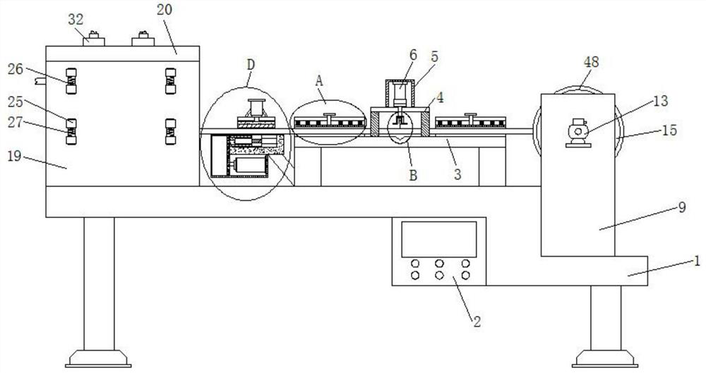
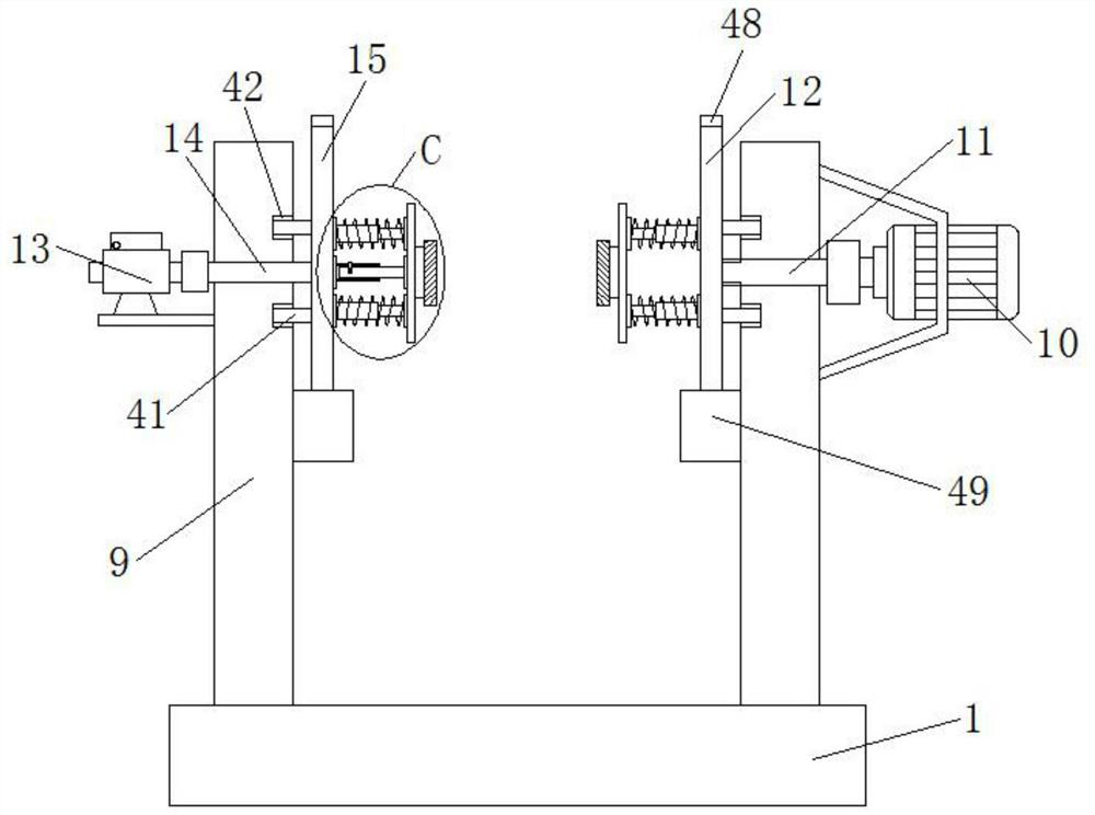
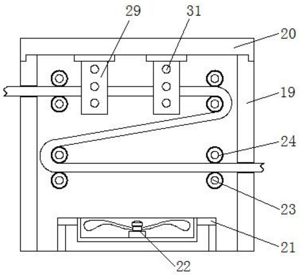
[0029] refer to Figure 1-11 , a cable manufacturing equipment, comprising a workbench 1, a PLC controller 2 is installed at the lower end of the workbench 1, a cooling box 19 is installed on the left side of the upper end of the workbench 1, and a box cover 20 is provided at the upper end of the cooling box 19, and the workbench The left side of the upper end of 1 is equipped with a third support frame 21 that matches the position of the cooling box 19, and a cooling fan 22 is installed on the upper end of the third support frame 21, and both sides of the inner cavity of the cooling box 19 are arranged symmetrically. There is a movable shaft 23, and the outside of t...


PUM


Abstract

The invention relates to the technical field of cables manufacturing, in particular to cables manufacturing equipment. The cables manufacturing equipment comprises a workbench, a PLC controller is arranged at the lower end of the workbench, and a first supporting frame is arranged in the middle of the upper end of the workbench, and a second supporting frame is arranged in the middle of the upperend of the first supporting frame; a fixing cover is connected to the middle of the upper end of the second supporting frame, a first electric hydraulic cylinder is arranged at the upper end of the inner cavity of the fixed cover, the lower end of the first electric hydraulic cylinder penetrates through the second supporting frame through a hydraulic rod and extends below the first electric hydraulic cylinder, and a cutting blade is welded to the lower end of the first electric hydraulic cylinder through a fixing plate, side plates are symmetrically arranged on the right side of the upper endof the workbench, and a speed reducing motor is arranged on the outer side of one side plate. According to the cables manufacturing equipment, the structure design is reasonable, the functionality ishigh, the operation is convenient, and is convenient for effectively winding the cable just manufactured; the process interval time is shortened, the working efficiency is improved conveniently, and the situation that due to twining of wound cables, the use is affected is avoided.

Description

technical field [0001] The invention relates to the technical field of cable manufacturing, in particular to a cable manufacturing equipment. Background technique [0002] With the increase in the demand for electricity in all walks of life, the use of cables is becoming more and more extensive. Cables are used to transmit electric (magnetic) energy, information and wire products that realize electromagnetic energy conversion. The cables are composed of one or more mutually insulated A wire made of a single conductor and an outer insulation layer that transmits electricity or information from one place to another. [0003] At present, the functions of most existing cable manufacturing equipment are relatively single, and one device can only realize one function, which increases the number of cable manufacturing processes, increases the interval time between processes, and reduces the work efficiency of cable manufacturing equipment. During the manufacturing and winding proc...

Claims


Application Information

Patent Timeline
Patent Type & Authority Patents(China)
IPC IPC(8): B21F11/00B21F23/00B21C47/02B21C47/28B29C35/16H01B13/00
CPCB21C47/02B21C47/28B21F11/00B21F23/00B29C35/16H01B13/00
Inventor 不公告发明人
Owner 河北优艾斯电器有限公司
Learn More