
Road and bridge steel mould structure with high supporting performance

A technology of road and bridge and steel formwork, applied in the direction of bridges, bridge construction, erection/assembly of bridges, etc., can solve the problems of lack of auxiliary fixing mechanism, fixed installation, inconvenient T-shaped struts, etc., and achieve the effect of disassembly and maintenance.

Active Publication Date: 2021-09-07
CHONGQING JIANGJIN STEEL MOLD CO LTD
View PDF29 Cites 0 Cited by
  • Summary
  • Abstract
  • Description
  • Claims
  • Application Information

AI Technical Summary

Problems solved by technology

[0005] In order to make up for the deficiencies of the existing technology and solve the problems that the currently used road and bridge steel mold structure has certain defects and lacks auxiliary fixing mechanisms, it is inconvenient to fix and install the T-shaped strut, and it is inconvenient to disassemble and maintain the T-shaped strut. problem, the present invention proposes a road and bridge steel mold structure with good support

Method used


Image

  • Road and bridge steel mould structure with high supporting performance
  • Road and bridge steel mould structure with high supporting performance
  • Road and bridge steel mould structure with high supporting performance

Examples


Embodiment 1

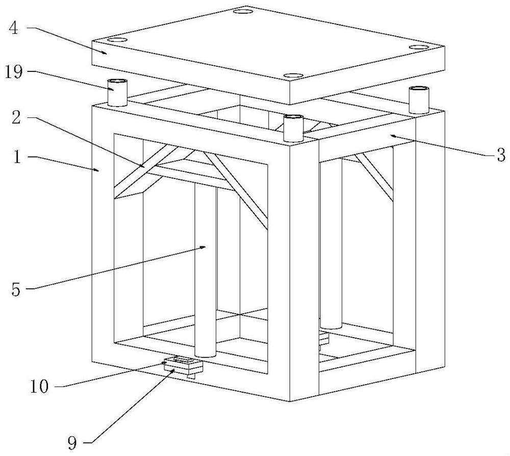
[0027] see Figure 1-4 As shown, a road and bridge steel mold structure with good support includes a square frame 1, a support block 2, a connecting rod 3, a top plate 4, a T-shaped strut 5 and a clamping mechanism; the square frame 1 is internally fixed symmetrically Install two support blocks 2, the square frame 1 is provided with two groups, the two groups of square frames 1 are fixedly connected by connecting rods 3, and the inner bottom of the square frame 1 is equipped with T-shaped struts 5. The left and right ends of the T-shaped strut 5 are attached to the two support blocks 2 respectively, the top plate 4 is installed on the top of the square frame 1, and the bottom end of the top plate 4 is attached to the top end of the connecting rod 3;

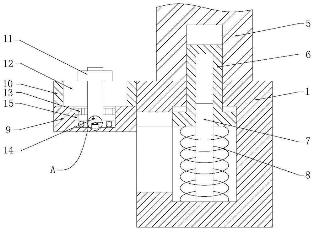
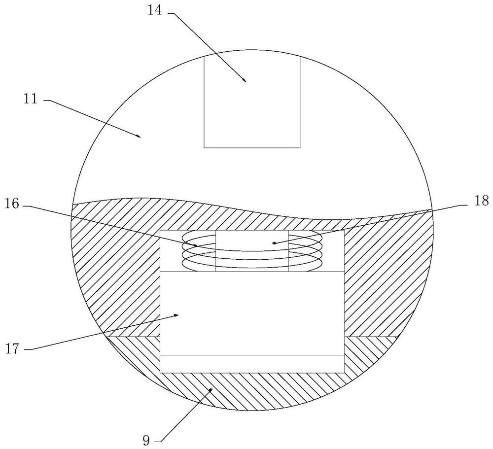
[0028]The clamping mechanism includes a T-shaped round bar 6, a guide rod 7, a spring 8, a fixed block 9, a fixed block 2 10, a T-shaped round block 11 and a square through groove 12, and the inner bottom of the square frame 1 A...

Embodiment 2

[0037] see Figure 5 As shown in Comparative Example 1, as another embodiment of the present invention, a support rod 26 is fixedly installed on the lower side of the rear end of the square frame 1, and an arc-shaped limit block 25 is installed on the top of the support rod 26, The annular side of the T-shaped strut 5 fits with the arc-shaped limit block 25, and the rear end of the support rod 26 is rotated with a rotating rod 27, and the upper side of the front end of the rotate rod 27 is in contact with the arc-shaped limit block 25. Fitting, the lower side of the front end of the rotating rod 27 is fixedly equipped with a fixed pin, the ring side of the fixed pin is equipped with a torsion spring two and a bearing, and the outer side of the torsion spring two and the outer side of the bearing are all fixedly installed inside the support rod 26, so A T-shaped block 29 is installed on the upper side of the rear end of the rotating rod 27, and the front end of the T-shaped blo...


PUM


Abstract

The invention belongs to the field of road and bridge steel molds, and particularly relates to a road and bridge steel mold structure with high supporting performance. The structure comprises a square frame, a supporting block, a connecting rod, a top plate, a T-shaped supporting rod, a T-shaped round rod, a guide rod, a first spring, a first fixing block, a second fixing block, a T-shaped round block, a square through groove, a first torsional spring, a first magnetic block, a second magnetic block, a second spring, a square block, an adjusting bolt, a cylindrical rod, a T-shaped inclined block, a third spring, a conical block, a fourth spring, an inner hexagon bolt, an arc-shaped limiting block, a supporting rod, a rotating rod, a clamping block, a T-shaped block, a fifth spring and a magnetic ring. The first fixing block moves to drive the T-shaped round block to move and penetrate through the square through groove in the second fixing block, then the T-shaped round block is screwed reversely, so that the first magnetic block is separated from the second magnetic block, under the effect of torsion of the first torsion spring, the T-shaped round block rotates to be attached to the top end of the second fixing block, and then the positions of the first fixing block and the T-shaped round rod are fixed.

Description

technical field [0001] The invention relates to the field of steel molds for roads and bridges, in particular to a steel mold structure for roads and bridges with good support. Background technique [0002] Bridge steel formwork is a steel formwork specially used for erecting railway or highway bridges. It is widely used in construction projects because of its multiple uses and beautiful concrete pouring. It is in line with the policy of "substituting steel for wood" in our country. [0003] The support blocks inside the road and bridge steel formwork structure are convenient to prop up the inside of the square frame, avoiding the deformation of the square frame due to excessive pressure. The design of the T-shaped brace is convenient for supporting the support blocks. The pressure can be evenly distributed on the square frame and connecting rods. [0004] There are certain defects in the steel formwork structure of the road and bridge currently used. The lack of auxiliar...

Claims


Application Information

Patent Timeline
Patent Type & Authority Applications(China)
IPC IPC(8): E01D21/00
CPCE01D21/00
Inventor 李彬
Owner CHONGQING JIANGJIN STEEL MOLD CO LTD
Learn More