Acid-resistant and oil-resistant oil cylinder rack

A rack and oil technology, applied in the direction of fluid pressure actuation devices, can solve the problems of high efficiency, inconvenient installation, disassembly and maintenance, etc., and achieve the effects of high efficiency, long service life and wide application range

Inactive Publication Date: 2016-07-27
JIANGSU LEADER PRECISION MACHINEY SALE CO LTD
View PDF6 Cites 0 Cited by
  • Summary
  • Abstract
  • Description
  • Claims
  • Application Information

AI Technical Summary

Problems solved by technology

[0006] Purpose of the invention: The purpose of the invention is to provide an acid-resistant and oil-resistant oil cylinder frame, which has a reasonable design structure, an alloy stainless steel integral structure with the characteristics of acid resistance, wear resistance and oil resistance, long service life, and high efficiency without frequent maintenance. It solves the problem of inconvenient installation, disassembly and maintenance of the assembly frame of the mechanical drive parts of the existing hydraulic cylinder, and has a wide range of applications

Method used


Image

  • Acid-resistant and oil-resistant oil cylinder rack
  • Acid-resistant and oil-resistant oil cylinder rack
  • Acid-resistant and oil-resistant oil cylinder rack

Examples


Embodiment 1

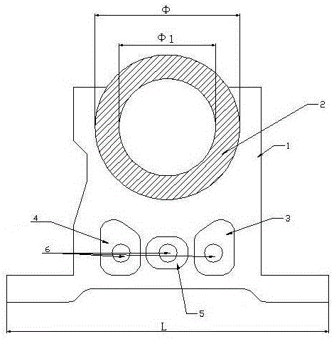
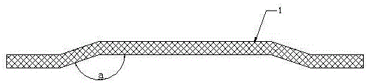
[0018] Such as figure 1 , figure 2 with image 3 The shown acid-resistant and oil-resistant oil cylinder frame includes a support plate 1, a limit ring 2 arranged on the support plate 1, and a first groove 3 arranged on the support plate 1 and below the limit ring 2, The second groove 4, the third groove 5, and the positioning holes 6 respectively arranged in the first groove 3, the second groove 4, and the third groove 5, wherein, one end of the support plate 1 is set as a plate-type concave Structure; the support plate 1, the first groove 3, the second groove 4 and the third groove 5 are integrally formed by alloy stainless steel; the length L of the plate concave structure at one end of the support plate 1 is 235mm-245mm, and the limit ring The outer diameter Φ of 2 is 70mm-80mm, and the inner diameter Φ1 is 105mm-115mm.

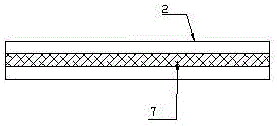
[0019] Further preferably, the acid-resistant and oil-resistant oil cylinder frame also includes a limit groove 7 arranged in the limit ring 2, which...

Embodiment 2

[0021] Such as figure 1 , figure 2 with image 3 The shown acid-resistant and oil-resistant oil cylinder frame includes a support plate 1, a limit ring 2 arranged on the support plate 1, and a first groove 3 arranged on the support plate 1 and below the limit ring 2, The second groove 4, the third groove 5, and the positioning holes 6 respectively arranged in the first groove 3, the second groove 4, and the third groove 5, wherein, one end of the support plate 1 is set as a plate-type concave Structure; the support plate 1, the first groove 3, the second groove 4 and the third groove 5 are integrally formed by alloy stainless steel; The outer diameter Φ is 75mm, and the inner diameter Φ1 is 110mm.

[0022] Further preferably, the acid-resistant and oil-resistant oil cylinder frame also includes a limit groove 7 arranged in the limit ring 2, which is connected with the limit protrusion of the oil cylinder during assembly to increase the connection stability; the support pla...


PUM


Abstract

The invention belongs to the technical field of mechanical drive part assembly accessory application, and particularly discloses an acid-resistant and oil-resistant oil cylinder rack. The acid-resistant and oil-resistant oil cylinder rack comprises a supporting plate, a limiting ring arranged on the supporting plate, a first groove, a second groove, a third groove and positioning holes, wherein the first groove, the second groove and the third groove are formed in the supporting plate and located below the limiting ring; the positioning holes are formed in the first groove, the second groove and the third groove; one end of the supporting plate is arranged into a plate type U-shaped structure; the supporting plate, the first groove, the second groove and the third groove are made from alloy stainless steel in an integral forming manner; the length L of the plate type U-shaped structure at one end of the supporting plate is 235 mm to 245 mm; and the outer diameter phi of the limiting ring is 70 mm to 80 mm, and the inner diameter phi of the limiting ring is 105 mm to 115 mm. The acid-resistant and oil-resistant oil cylinder rack has the beneficial effects that the design and the structure are reasonable, an alloy stainless steel integrated structure has the characteristics of being resistant to acid, abrasion and oil, the service life is long, frequent overhaul is not needed, and the using efficiency is high; and the problem that an existing hydraulic oil cylinder mechanical drive part assembled rack is not convenient to install or disassemble or maintain is solved.

Description

technical field [0001] The invention belongs to the application technical field of assembly parts of mechanical drive parts, and in particular relates to an acid-resistant and oil-resistant oil cylinder frame, which is suitable for fast, accurate and stable assembly operations of oil cylinders, and is acid-resistant and oil-resistant. Background technique [0002] The hydraulic cylinder is a hydraulic actuator that converts hydraulic energy into mechanical energy and performs linear reciprocating motion (or swinging motion). It has a simple structure and reliable operation. When it is used to realize reciprocating motion, the deceleration device can be eliminated and there is no transmission gap. , The movement is smooth, so it is widely used in various mechanical hydraulic systems. The output force of the hydraulic cylinder is proportional to the effective area of ​​the piston and the pressure difference on both sides; the hydraulic cylinder is basically composed of the cyl...

Claims


Application Information

Patent Timeline
Patent Type & Authority Applications(China)
IPC IPC(8): F15B15/20
CPCF15B15/20
Inventor 陆斌陆寅鹏
Owner JIANGSU LEADER PRECISION MACHINEY SALE CO LTD
Why Eureka
Try Eureka